Download
1 / 22
220 likes | 341 Vues
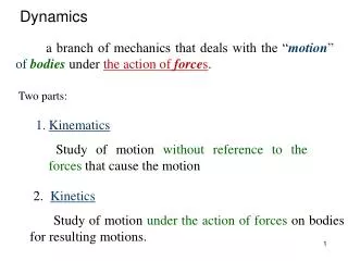
ANSS/NSMP STRONG-MOTION RECORD PROCESSING AND PROCEDURES. Christopher D. Stephens and David M. Boore US Geological Survey Menlo Park, CA. COSMOS/NSF International Workshop on Strong-Motion Record Processing May 26-27, 2004. Network consists of both analog (265) and digital (675) recorders

E N D
ANSS/NSMP STRONG-MOTION RECORD PROCESSING AND PROCEDURES Christopher D. Stephens and David M. Boore US Geological Survey Menlo Park, CA COSMOS/NSF International Workshop on Strong-Motion Record Processing May 26-27, 2004
Network consists of both analog (265) and digital (675) recorders • Installations include ground motion reference sites and structures • Located in 32 states and Puerto Rico, but about half are in California • About 320 have continuous or dial-up connections
Digitizing Analog Records • Scan in grayscale, 600 dpi (236pixels/sec) • Enhance image contrast (no smoothing) and convert to black and white • Semi-automatic trace following • Interpolate to 200 sps for output • Check for relative offsets and tilts of baselines for multi-segment traces • Correct baselines using robust L1 fit
Processing scheme is simple and ensures compatibility: • Baseline correction • End conditioning and padding • Acausal filtering of acceleration only • High cut cosine taper and instrument response correction in spectral domain • Low cut Butterworth filter in time domain • Integration to velocity and displacement in time domain • Compute response spectra • Review for physically reasonable result
Baseline shifts occur on recordings of strong and weak motion
Many possible causes • Mechanical: • Hysteresis (mechanical/ electrical) • “Popcorn” noise • Other • Ground deformation • Tilt near earthquakes • Differential settlement • Other • Analog-Digital Conversion (ADC)
Although the results look physically plausible, the residual displacements can be sensitive to t1, t2
Need for low-cut (high-pass) filtering • There can be many reasons for the shifts, and as a result it is not possible to design a single correction scheme • Residual displacements can be sensitive to parameters of baseline correction • Filtering is often required (and in many cases is all that is required) to remove unwanted low-frequency noise
Acausal filtering is preferred over causal • At periods much shorter than the corner period, both the waveforms and response spectra are less sensitive to the corner • Particularly true for inelastic response!
Choosing filter corners • Subjective • Often guided by shape of Fourier spectrum, but this can lead to excessive removal of long periods • Noise can be estimated from: - digitized fixed trace for analog records - pre-event of sufficient duration for digital • In many cases, digital instruments allow choice of filter corners longer than periods of engineering interest, but peak displacement may be sensitive to the filter corner
Conditioning for bandpass filter • Values extending inward from each end and up to first zero-crossing are set to 0. • Pads are added symmetrically to both leading and trailing edges to accommodate filter transients • Pad length at each end is determined from the empirical relation: tpad = 1.5 * nroll / fc • Pads are removed after final processing
Selecting filter order is a compromise between: • Effectively removing unwanted long-period noise • Avoiding the introduction of excessive ringing by using too high an order
Uniform filtering (same filter corners and rolloff) is usually applied to all channels from a particular site or structure • Disadvantage is that long-period content is controlled by channel with weakest signal • But motions involving more than one channel (e.g., inter-story drift, torsion) can be computed directly from processed records
One method used to validate choice of filter parameters is to compare long-period waveforms at nearby stations Mw 7.2 Hector Mine D = 160 km, inter-station = 1.6 km