Download
1 / 7
70 likes | 164 Vues
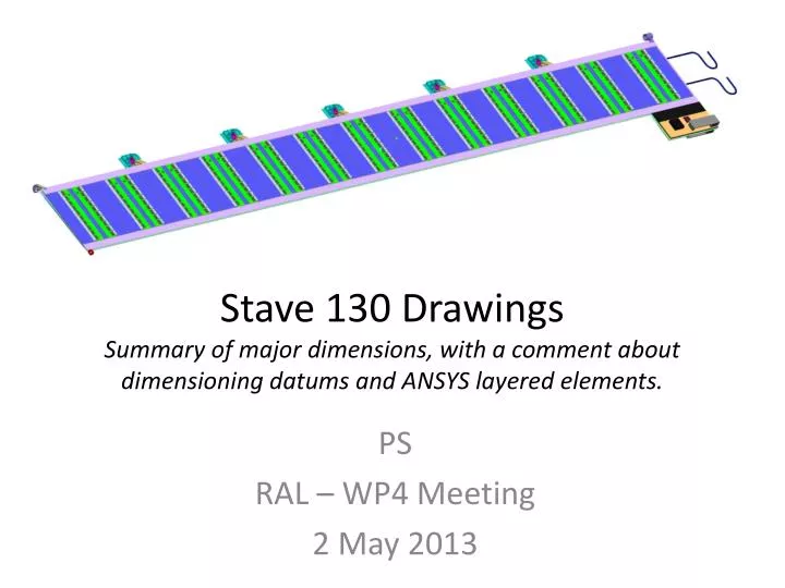
Stave 130 Drawings Summary of major dimensions, with a comment about dimensioning datums and ANSYS layered elements. PS RAL – WP4 Meeting 2 May 2013. Stave Dimensions. Critical Dimensions: Overall Length 1277

E N D
Stave 130 DrawingsSummary of major dimensions, with a comment about dimensioning datums and ANSYS layered elements. PS RAL – WP4 Meeting 2 May 2013
Stave Dimensions Critical Dimensions: • Overall Length 1277 • Width 120 (likely to change, hopefully narrower, due to modifications with hybrid) • SMC area 100 x 50 • EOS at Z=0 to Silicon Edge 0.1mm • Start of Silicon from Z=1277.1 = 3.36 • Module to Module Gap 0.46mm • Pitch of Modules 98mm
Stave thicknesses • Wirebond to Wirebond 7.88 • ASIC to ASIC 6.18
Stereo Side • Pitch of Modules 98mm • EOS at Z=0 to Silicon Edge 0.102mm • Module to Module Gap 0.3817 All dimensions theoretical to show difference!
Dimensioning Datums NOTE: The tape is not to be used as a datum. The tape will be positioned to a nominal accuracy in order for the wire bond pad to be ‘within tolerance’ Laser drilled hole in Z=0 locator foil.
Thoughts about ANSYS carbon fibre modelling • ANSYS 14 has stopped ‘supporting’ certain elements. • There are 2 elements which can be used for layered analysis • SHELL181 • SOLID185 • ANSYS has a ‘Section’ menu, one of which is Shell, where you can construct a layup. This menu seems to work for solid as well as shell elements. • It seems the layup can only be associated with 1 coordinate system.