Download
1 / 33
330 likes | 405 Vues
Team 16. Critical Current Probe. Amy Eckerle Andrew Whittington Philip Witherspoon. Final April 2012. NHMFL Applied Superconductivity Center. Overview. Background Introduction The Project Objectives Constraints Concepts Final Design Project Plan Manufacturing and Assembly

E N D
Team 16 Critical Current Probe Amy Eckerle Andrew Whittington Philip Witherspoon Final April 2012 NHMFL Applied Superconductivity Center
Overview • Background • Introduction • The Project • Objectives • Constraints • Concepts • Final Design • Project Plan • Manufacturing and Assembly • Economics • Results • Environmental Issues
Super Conductivity • Superconductivity is a phenomenon that allows an indefinite amount of current to flow with negligible resistance.
Critical Current • Critical Current Probes measures how much current a sample can take before it becomes non-superconducting • Temperature • Magnetic Field • Orientation
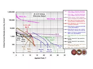
Samples • Sample are made of YBCO • HTS (High Temperature Superconducting) • Samples are mounted at the base of two current leads running the length of the probe • Submerged in cryogenic liquid
The Project • Design a critical current probe to conserve the amount of liquid helium used during a critical current measurement test • $5/liter of liquid He Stainless Steel Jacket Current Leads Cryostat Voltage tap wire Helium level Voltage tap Sample Magnet
Objectives • Conserve Helium • Test 6-8 short samples • Test one spiral sample • Deliver 1000 Amps to the samples • Durability
Constraints Current Leads • Constraints • Budget of $4000 • Constant casing diameter • Minimum length to reach center of cryostat Stainless Steel Jacket Cryostat
Concepts Ways to Reduce Helium Consumption Heat Exchanger HTS Leads and support Number of Leads Fins Gas Insulation Jacket Design
Solutions HTS Leads and support • Low thermal conductivity with high electrical conductivity • Great reduction in copper surface area • Prevents copper leads from entering liquid helium bath G10 Support HTS Lead
Solutions Current Leads Number of Leads • Leads are major heat leak • Maintain 8 samples with 6 leads
Solutions Current Leads Jacket Design • interrupts thermal conduction of the stainless steel tube Stainless steel portion G10 portion
Manufacturing and Assembly • Machining • ASC shop • NHMFL shop • Exotic Machining, Inc • Assembly • Top flange • Stainless steel tube • Spacer • Copper leads • Current connects • G10 connector • Sample holder • Soldering of HTS leads • HTS support system • Voltage taps
Manufacturing and Assembly • Assembly • Top flange • Stainless steel tube • Spacer • Copper leads • Current connects • G10 connector • Sample holder • Soldering of HTS leads • HTS support system • Voltage taps
Soldering of HTS Leads • Special device was created to solder 8 HTS tapes together • Soldering to copper leads using various heating methods
Economics • Budget of $4000
Preparing • Applied voltage taps along the probe • Soldered a strip of HTS to complete circuit • Covered base with G-10 to protect HTS
Testing • Took place the NHML • Lifted by crane into cryogenic bath • Preliminary testing • To make sure HTS Lead was superconducting • Final testing in Liquid helium to measure burn off
Environmental/Safety Hazards • G-10 • Flux • Cutting Fluid • Machining Hazards • Heating Hazards • Handling Liquid Helium • Electric Current • Weight G-10 Flux
Results • Preliminary test results (in liquid nitrogen) • Took place after 12pm 4/5/12 • Future testing (in liquid helium) • Will take place at NHMFL 4/6/12
Conclusions • Testing in liquid nitrogen will completed on two leads • Full testing will be completed on 4/5/12 if the preliminary is successful
Acknowledgments Dr. Hovsapian, Adjunct Faculty, Florida State University, Mechanical Engineering, Ph.D. Dr. Kosaraju, Adjunct Faculty and Postdoctoral Researcher Dr. Hellstrom, Ph.D. Materials Science, Stanford University, Dr. Trociewitz, Associate Scholar/Scientist, ASC Applied Superconductivity Center NHMFL Bill Sheppard, NHMFL Machine Shop Robert Stanton, NHMFL Bill Starch, ASC Machine Shop Dimitri Argonaut, ASC Machine shop
References Çengel, Yunus A., Robert H. Turner, and John M. Cimbala. Fundamentals of Thermal-fluid Sciences. Boston: McGraw-Hill, 2008. Print. Ekin, Jack W. . Experimental Techniques for Low-temperature Measurements. New York: Oxford UP, 2006. Print. Thomas, Lindon C. Fundamentals of Heat Transfer. Englewood Cliff, NJ: Prentice-Hall, 1980. Print.