Download
1 / 31
310 likes | 467 Vues
Radio Frequencies. Oscillator. Feedback loop. Oscillator. As the output of the amplifier is fed to the input, feedback or oscillation occurs. Tuned Oscillator. Oscillator. When properly tuned to a high enough frequency, the oscillator will produced radio frequencies

E N D
Oscillator Feedback loop
Oscillator • As the output of the amplifier is fed to the input, feedback or oscillation occurs
Oscillator • When properly tuned to a high enough frequency, the oscillator will produced radio frequencies • Frequencies begin to take on the characteristics of radio frequencies (RF) at about 30,000 KHz • RF can travel great distances, and can be modulated to carry information (audio & video)
RF • Antennae are conductive rods that will easily radiate RF • When the output of the oscillator is connected to an antenna, the electrons in the antenna begin to vibrate or oscillate at RF frequencies • Waves of electromagnetic radiation will emanate from the antenna at those RF frequencies (+30KHz)
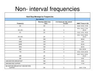
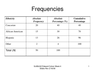
RF spectrum • Very Low Frequencies – 3 – 30 KHz • Low Frequencies 30 – 300 KHz • Medium frequencies 300 KHz – 3 MHz • High frequencies 3 – 30 MHz • Very High frequencies 30 MHz – 300 MHz • Ultra High frequencies 300 MHz – 3 GHz • Super High frequencies 3 – 30 GHz • Extremely High frequencies 30 – 300 GHz
RF and beyond • As particles continue to accelerate, creating waves of decreasing wavelengths, energy takes on other characteristics • Infrared • Visible light – red, orange, yellow, green, blue, indigo, and violet • Ultraviolet • X-rays • Gamma rays • Cosmic rays
Spectrum management • AM radio (MF) – 535 – 1705 KHz • Channels are 10 KHz • Radio receivers tune to the center frequency in the channel or carrier 540 560 550 565 535 545 555
Spectrum management • FM radio (VHF) – 88 – 108 MHz • Channels are 200 KHz • Radio receivers tune to the center frequency in the channel or carrier 88.1 88.2 88.0 +/- 75 KHz deviation
Spectrum management • TV (VHF and UHF) • Channels are 6 MHz • TV receivers tune to the center frequency in the channel or videocarrier • In this example: Channel 6 83.25 MHz video carrier (1.25 MHz above lower edge of channel) 88.0 82.0 (Audio 4.5 MHz +/- 25 KHz) (30 KHz above lower edge of channel)
Spectrum management • http://frrl.files.wordpress.com/2010/11/frequency-allo-chart.jpg
Calculating wavelength Velocity WL = Frequency Velocity = speed of light = 300,000,000 meters per second
Calculating wavelength 300,000,000 WL = Frequency
Calculating wavelength 300,000,000 WL = 102,500,000 WHIZ-FM – 102.5 MHz
Calculating wavelength 300,000,000 2.93 = 102,500,000 Radio wave is 2.93 meters from crest to crest
Calculating wavelength 300,000,000 2.93 = 102,500,000
Calculating wavelength 300,000,000 WL = 1,240,000 WHIZ-AM – 1240 KHz
Calculating wavelength 300,000,000 241.93 = 1,240,000 Radio wave is 241.93 meters from crest to crest
Calculating wavelength • Higher frequencies = shorter wavelengths • In the highest bands of the usable spectrum, wavelength are measured in nanometers or angstroms • Wavelengths in the “microwave” bands are so short that atmospheric moisture affects transmission
Calculating wavelength • These calculations are used to determine ideal antenna length • In FM and TV, antennae use half-wave dipole construction • The antenna is one-half the length of the wave, and the pole is cut in half
Half wave dipole “Stacking” the elements forces waves toward horizon. This adds gain to the antenna.
Quarter-wave vertical • In AM, the longer wavelengths dictate the use of quarter-wave vertical antennae • The tower itself becomes the antenna • AM also uses a ground array to propagate the ground waves
How waves behave • HF and above (FM, TV, satellite, etc.) travel in direct waves, or line-of-sight • Direct waves will not “bend” or pass through solid objects • LF and MF frequencies travel in sky waves, which bounce off the ionosphere • LF and MF frequencies travel in ground waves, which follow the curvature of the earth
Antenna location • Best location for an FM or TV antenna is on the highest unobstructed hill, building, tower, peak • Best location for an AM antenna is low marshy location
Antenna schematics AM antenna FM antenna
Ionosphere • A layer of the atmosphere where hydrogen atoms become “ionized” • Ionization occurs when the hydrogen atoms become “charged” because they give up electrons • Heating of the ionosphere by the sun causes the ionization • The will determine the behavior of sky waves
Sky waves • May be absorbed during the daylight hours • May pass through during the daylight hours • May be reflected at night when the ionosphere cools
Sunspots • Affect terrestrial communication, telecommunications, broadcasting, computers, other electronics • Occur in 11 year cycles • Activity builds and subsides slowly 1990 2000 2010