Download
1 / 23
240 likes | 391 Vues
Supported by. Fueling Requirements for Steady State Spherical Torus Operation. Roger Raman, Thomas R. Jarboe, + Henry W. Kugel University of Washington, Seattle + Princeton Plasma Physics Laboratory Joint Meeting of the 3rd IAEA technical Meeting on Spherical Torus

E N D
Supported by Fueling Requirements for Steady State Spherical Torus Operation Roger Raman, Thomas R. Jarboe, +Henry W. Kugel University of Washington, Seattle +Princeton Plasma Physics Laboratory Joint Meeting of the 3rd IAEA technical Meeting on Spherical Torus and the 11th International Workshop on Spherical Torus 3-6 October 2005, St Petersburg, Russia Work supported by DOEgrant No. DE-FG03-02ER54686 Raman,11 STW 3-6 Oct 2005
Early Work on CT Injection • Perkins (LLNL) and Parks (GA) proposed concept for fueling -[Perkins, Ho, Hammer, NF 28, 1365 (1988) & Parks, Phys. Rev. Lett. 61, 1364 (1988)] • Hammer and Hartman (LLNL) developed the accelerator concept -[Hammer and Hartman, Phys. Rev. Lett., 61, 2843 (1988)] • First tokamak fueling (CT size < Tok. size) -[Raman et. al,. Phys. Rev. Lett. 73, 3101 (1994)]. Raman,11 STW 3-6 Oct 2005
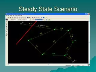
Outline of Talk • Spherical Torus has high beta and high bootstrap frac. • Optimized profiles • Present systems may be inadequate • Pellets sizes are large & injection is shallow • No plan at present for density profile control • Density profile control ideal method for steady burn control • Compact Toroid (CT) injection system has potential for density profile control and momentum injection • Status of current work • Open issues • Plans and suggestions Raman,11 STW 3-6 Oct 2005
Flexible fueling system may be the only choice for burn control in steady-state ST discharges • A burning plasma device has no need for neutral beam injection for plasma heating and alphas are isotropic →no momentum injection • In a device with high bootstrap current fraction, optimized density and pressure profiles must be maintained →fueling system must not adversely perturb established density and pressure profiles • Other than a system for current drive, a fueling system is all that a burning plasma system may be able to rely on to alter core plasma conditions and for burn control • Fusion power output scales as the square of density • Initial density peaking via. core fuelling provides more flexibility to reach ignition Raman,11 STW 3-6 Oct 2005
Fueling profiles from present systems • Pellets (< 1km/s, HFS) • Large pellets increases density over a large radius • Capability of small pellets for profile control yet to be established • Supersonic gas (~ 2-3 km/s) • Fuels from the edge with improved fueling efficiency • Capability for profile control not known yet • Plasma jet (~ 30km/s) • Similar to supersonic gas, bulk fueling at present • Penetration into large cross-section plasmas not known Raman,11 STW 3-6 Oct 2005
In a CT injection system a CT is accelerated to high velocity and injected into the target plasma to achieve deep fueling CT Penetration time: few µs CT Dissociation time: < 100 µs Density Equilibration time: 250 - 1000 µs Variable Penetration depth: edge to beyond the core Raman,11 STW 3-6 Oct 2005
CTs formed in a magnetized Marshall gun on fast (~10 µs) time scales Raman,11 STW 3-6 Oct 2005
A CT Fueller forms and accelerates CTs in a coaxial rail gun in which the CT forms the sliding armature Raman et al., Fusion Techn., 24, 239 (1993) • Amount of gas injected controls CT density • Applied voltage controls CT velocity • Control system specifies fuel deposition location for each pulse Raman,11 STW 3-6 Oct 2005
Status of current workTdeV tokamak discharges beneficially fueled by CTs, without causing any adverse perturbation TdeV R = 0.86m a = 0.25m BT = 1.4T Ip = 160kA Raman,11 STW 3-6 Oct 2005
JFT-2M results (IAEA 2002) K.Tsuzuki et al., EX-C1-1, Proc. IAEA 2002, Lyon, France Raman,11 STW 3-6 Oct 2005
Conceptual study of a CT system for ITER yields an attractive design <1% particle inventory perturbation, 20 Hz operation R. Raman and P. Gierszewski, ITER Task D315 (1997), Fusion Engin. & Design 39-40 (1998) 977-985 Raman,11 STW 3-6 Oct 2005
ITER CT Injector parameters CT radius 0.1 m CT length 0.2 m CT density (D + T) 9 x 10²² m-3 CT mass 2.2 mg DT (2.6 T2) Fueling rate (D + T) 5.3 x 10²⁰ / pulse Fueling frequency ≤ 20 Hz CT velocity 300 km/s CT kinetic energy 100 kJ (120 kJ T2) Momentum inj. rate 13.2 kg.m/s DT, 15.6 T2, Power consumption 8 MWe (10 T2) (Raman and Gierszewski, Fusion Engin. Design 39-40 (1998) 977 & ITER Task D315) Raman,11 STW 3-6 Oct 2005
Open Issues Previous experiments too small to study localized core fueling Approximate relative sizes of various target plasmas and CTs. A CTF sized CT will do far more localized fueling on a NSTX sized device - Steep BT more precisely determines CT stopping location Ref: R. Raman and K. Itami, Journal of Plasma and Fusion Research, 76. 1079 (2000) Raman,11 STW 3-6 Oct 2005
Proposed research Plan • Injection into a large cross-section, low field device (eg., NSTX) - using an existing injector • Establish localized fueling (~ 2 yr) - Transport studies • Establish momentum injection (~ 2 +1 yrs) • Establish multi-pulse fueling (~3 + 1 yrs) • Intermediate scale experiments (JT-60U,JET) • Conduct burning plasma injector design • Re: design study for JT60U(R. Raman and K. Itami, Journal of Plasma and Fusion Research, 76. 1079 (2000)) Raman,11 STW 3-6 Oct 2005
The CTF-II injector (in storage at PPPL) Raman,11 STW 3-6 Oct 2005
The CT Formation bank power supply (110V AC input) Raman,11 STW 3-6 Oct 2005
A CT injector could provide profile control capability Raman,11 STW 3-6 Oct 2005
The ability to inject CTs significantly expands NSTX experimental capability • Precise H-mode initiation capability valuable for on-going XPs • Electron Transport Barrier studies • Transport studies by isotopic impurity tailoring • Reconnection studies • Momentum injection studies for transport barrier sustainment • Precise density profile control needed for NSTX SS discharges • Local current injection to suppress NTMs ? Raman,11 STW 3-6 Oct 2005
Conclusions • A CT injector has the potential to deposit fuel in a controlled manner at any point in the machine • In a Steady State ST device with only RF for current drive, a flexible fueling system may be the only internal profile control tool • Inject momentum for plasma beta and stability • Precise density profile control to optimize bootstrap current and to maintain optimized fusion burn conditions • Study core transport in present machines (He ash removal studies, ELM control) • Large STs should consider and develop backup options to meet the fuelling requirements of future devices • Large STs are an attractive target for developing CT fueling • Steep BT gradient, large crossection Essential CT data needed for an ITER CT injector design could be obtained on NSTX using an existing injector Raman,11 STW 3-6 Oct 2005
No evidence for metallic impurity contamination of TdeV Raman,11 STW 3-6 Oct 2005
Edge fueling of diverted discharges triggers improved confinement behavior Raman,11 STW 3-6 Oct 2005
Inductive quality discharge produced by electrode discharge Raman, et al., NF 45 (2005) L15-L19 Raman,11 STW 3-6 Oct 2005
CT induced confinement improvement also seen on STOR-M* STOR-M R = 0.46 m A = 0.12 m Ip = 20 kA BT = 1T C. Xiao, A. Hirose, R. Raman, 2001, Compact Torus Injection Experiments in the STOR-M Tokamak, Proc. of 4th Symp. on Current Trends in International Fusion Research: Review and Assessment (Washington D.C., March 12-16, 2001, in print) * Recent similar results on JFT-2M Raman,11 STW 3-6 Oct 2005