Download
1 / 15
300 likes | 2.55k Vues
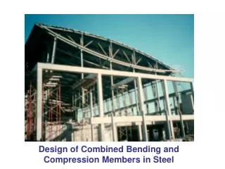
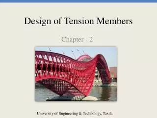
Design of Steel Tension Members. What is the maximum P? LRFD Equation. P. P. Design of Steel Tension Members. Equations for strength of tension members: For yielding in the gross section: For fracture in the net section:. Design of Steel Tension Members. Yielding in the gross section:.

E N D
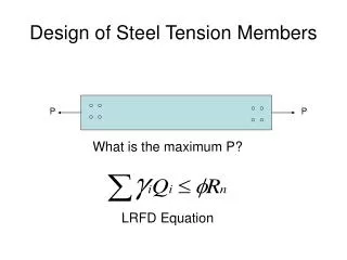
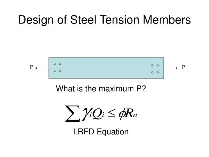
Design of Steel Tension Members What is the maximum P? LRFD Equation P P
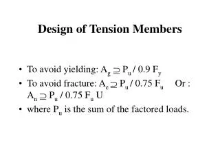
Design of Steel Tension Members Equations for strength of tension members: • For yielding in the gross section: • For fracture in the net section:
Design of Steel Tension Members • Yielding in the gross section: Max stress Fy P P Max stress Fu P P
Variable Definitions • Resistance factor, = 0.90 for yielding (p. 2-12 LRFD) = 0.75 for fracture • Fy = Yield Strength (p. 2-24 LRFD) • Fu = Tensile or Ultimate strength (p. 2-24 LRFD) Areas defined in Chapter B, Design Requirements
Design Requirements • Ag – Gross cross-sectional area • Ae – Effective net area If tension load is transmitted directly to each of the cross-sectional elements by fasteners or welds: • Ae = An • An = Net cross-sectional area (gross-section minus bolt holes)
Design Requirements If tension load transmitted through some but not all of the cross-sectional elements: by fasteners, Ae = AnU by welds, Ae = AgU or Ae = AU
Example of tension transmitted by some but not all of cross-section L –shape with bolts in one leg only Reduction coefficient, Where is the connection eccentricity(p. 16.1-177)
Tension Analysis Example Determine the factored strength of a 12” x 1.5”, A36 steel plate connected with one row of 4 – ¾” diameter bolts positioned transversely in a single line. A36, 1½” PL 12 in.
Design Example ( top p. 9 notes) Design a 1000 mm long splice plate to carry a tensile live load of 130 kN and dead load due to a mass of 4500 kg. The bolts will be ¾” in diameter and there will be at least three of them in a row parallel to the direction of force at each end. Space constraints require you to keep the width of the plate ≤ 100 mm. Use A36 steel in conformance with the rest of the building.
Design Example ( bottom p. 9 notes) Design a tension member for a live load of 67.4 kips and a dead load of 22.0 kips. It is part of a web system of a truss and will be 14.8 ft long between connections. The end connections will require two rows of ¾” diameter bolts, with three bolts per row. As a truss web member, an angle section seems most appropriate. Use A36 steel to conform to the rest of the truss. :
Design Example (p. 10 notes) Same as previous example but with double angles back to back. Assume that they will be bolted to 3/8 in. thick gusset plates, straddling them at each end. 3/8 in. gusset plate
Net Section for Staggered Bolt Holes Recall definition of Net Area, LRFD p. 16.1-10
Staggered Bolt Hole Example(p. 12 notes) Consider the 7 x 4 x ½ angle shown. The holes are 7/8” diameter, on normal gage lines. The holes are the U.S. standard 3” c.c. in each row, but the holes in the interior row in the 7” leg are offset by 1 ½ “ from the other holes, which line up with each other. Find An for both a two hole and a three hold tear line.