Download
1 / 55
1.1k likes | 2.36k Vues
PERMEABILITY AND CAPILLARITY. Pavement. Ice lenses fed by capillary water from water table. Original ground surface. Frozen soil. GWT. Capillary rise and frost action. CAPILLARITY. Movement of soil moisture through small pores.

E N D
PERMEABILITY AND CAPILLARITY
Pavement Ice lenses fed by capillary water from water table. Original ground surface Frozen soil GWT Capillary rise and frost action
CAPILLARITY • Movement of soil moisture through small pores. • Pores serve as capillary tubes and soil moisture rises above GWT. • Water held in this manner is in a state of suction or negative pressure. • Heightofcapillary risedepends on soil type, the finer the voids the greater the height. • Capillary water is continuously connected to the GWT • It rises up against the force of gravity due to capillary action. • It can be removed by drainage only. • Water in the capillary fringe (zone) held by surface tension forces, cannot be drained by any drainage system, because capillary flow does not obey the law of gravity. • If the GWT is lowered, the whole capillary fringe can be lowered. • Capillary water can also be removed by evaporation. • In cohesive soils its decreases cohesion and stability and the soil is transferred into a plastic state. • In sandy soils it adds to the stability provided the soil is laterally confined. • Height of capillary rise varies inversely with size of pores, which is a function of the particle size and density of soil. • Up to this height above the water table the soil is sufficiently close to full saturation. • The capillary height is determined by capillarimeter.
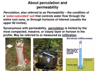
h = capillary rise. r = radius of tube. Downward gravityforce = wt. of the liquid column in the tube = w(r2h)---- 1 T = surface tension force per unit length = Contact angle Upward surface tensionforce = T 2r cos --2 Fig: Capillary rise in a tube above the free water surface.
Water will stop rising, when the upward force will be balanced by the downward force. w (r2 h) = 2T r cos (3) Equation shows that h increases as r decreases. It may be noted that for pure water in contact with clean glass the value of angle = 0. The equation is then simplified as: (4) The value of T at room temperature is 0.064 N/m or 73.0 dynes/cm. In applying the development of capillary rise in tubes to capillary rise in soil these values of T are sufficiently accurate for many practical problems. Equation for capillary rise can be expressed as: (5) d = Effective capillary diameter = 1/5 D10
Terzaghi and Peck (1948) equation for capillary rise (6) Where, hc max. is in millimeter, C is a constant depending upon the shape of the grains and the surface impurities (varying from 10.0 to 50.0 mm2) and D10 is the effective size expressed in millimeters. Approximate capillary height for different soil types.
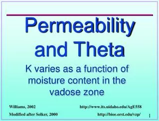
CAPILLARY MOVEMENT IN SOIL • Soil moisture moves continuously, even through unsaturated soils. • Direction of movement depends on the relative potential. • Moisture moves from higher potential towards lower potential. • The demand of a moist soil for additional moisture above GWT and the gravitational pull provide the principal potentials, which influence moisture movement. • Demand or capillary attraction for water is exerted in all directions. • Therefore capillary water may also move horizontally in soil depending upon the relative potential. • GWT is a free water surface at which the pressure is atmospheric. • For unsaturated soil, the capillary potential is always negative while in a saturated soil, it is zero. • Water therefore rises above the GWT. • When the capillary potential is balanced with the gravitational potential, capillary moisture will be in static equilibrium, and no flow will occur. • Fieldmoisture seldom reaches a state of equilibrium, because of relatively slow rate of capillary movement and the continuously changing weather conditions. • During dry season upper soil is drier with low capillary potential than lower soil and upward movement occurs. After rain fall, downward movement due to combined effect of gravity and capillarity takes place.
IMPORTANCE OF CAPILLARITY IN CIVIL ENGINEERING • Moisture increases due to capillary rise. • An increase of moisture always reduces the strength of soil (especially fine grained soil). • Study of capillarity is important for the following projects. Pavement Sub-grade • Sub-grade performance is much influenced by capillary water. • Pavement provides an impervious cover on the sub-grade. • Due to pavement, rain water is kept out of sub-grade soil, and evaporation and transpiration are prevented. • Pavement also reduces the range and frequency of changes of temperature in the underlying soil. • These conditions help the establishment of equilibrium with the ground water table. • As a result moisture tends to accumulate in a pavement sub-grade after the pavement is laid.
Such accumulation occurs slowly and requires 3-5 years. • Consequently he soil loses its shear strength. • If the study indicates the possibility of increase of capillary moisture to alarming level, techniques to avoid the accumulation of capillary moisture (within the zone of higher stresses below the pavement) are adopted. • Techniques include, • Provision of impermeable membrane • Drainage layer • at a design level (depth) to stop the rise of capillary moisture above that level. Excavations • Additional bonding force within particles is developed due to negative capillary potential. • This bonding force is known as apparent cohesion. • Apparent cohesion permits short term deepexcavation in fine grained soil without support. • Apparent cohesion however disappears with loss of capillary potential and the excavation may collapse. • Shallow trenches in moist sand without support are also possible due to negative capillary potential, while in dry and saturated sand trenches without support can not may made.
Fig: Different zones of capillary water, capillary potential and capillary movement.
Capillary Siphoning Fig: Capillary siphoning in dams above the impervious core To prevent the loss water, the crest of the impervious core should be kept sufficiently high.
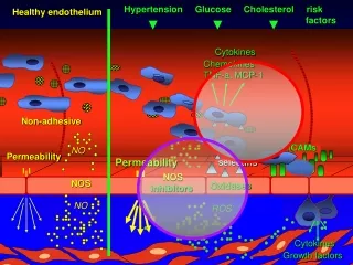
FACTORS AFFECTING CAPILLARITY OR CAPILLARY POTENTIAL • Capillary potential depends on surface tension of water and the radii of curvature of the air-water surfaces of the tiny wedges of water between the soil particles. • The amount of soil water to affect the radii of curvature depends on the following, • Particle size, • Density, • Temperature, • Degree of wetting in terms of angle of contact, • Percentage of dissolved salts in the soil water. • Effect of Particle Size • For same moisture content in a fine and coarse soil, the fine soil due to more surface area will have more points of contacts between the soil particles. • At each point of contact, less water will be collected and the radii of curvature and the corresponding surface tension will be greater. A lower capillary potential and a greater attraction for moisture is observed in fine grained soils as compared to coarse-grained soils.
2. Effect of Soil Density • If two particles of moist soil are packed closer, the meniscus curvaturewill be reduced, lowering the surface tension and increasing the capillary potential, resulting in lesser attraction for water. • When a relatively dry soil mass is sufficiently compressed it become saturated, although the moisture content remain unchanged. • The capillary potential, which initially was negative in loose state, increases to the maximum value of zero on densification. Actually the process of densification gradually reduces the curvature of air-water interfaces; and, finally, no curvature remains at saturation. • Hence the capillary potential increases with increase of density. 3. Effect of Temperature The surface tension varies inversely with temperature. A decrease in temperature increases surface tension and hence the capillary potential is reduced.
4. Effect of Angle of Contact • The angle of contact between the menisci and the soil particles depends on the mineral composition of soil. • An increase in the angle of contact will show low degree of wetting and hence tend to decrease the curvature of the menisci and thereby increase the capillary potential of soil at that particular water content. • A soil with an angle of contact greater than zero will have less attraction for water than a soil in which the particles are completely wetted. 5.Effect of Dissolved Salts • An increase in percentage of dissolved salts in soil water increase its surface tension, and reduces the capillary potential, and hence indicate more attraction for moisture. However the effect of dissolved salts is very small.
Fig. Influence of state of packing of soil on curvature of air-water interface. (a) Closely-packed soil; (b) Loosely-packed soil. Fig. Influence of wettability of soil grains on curvature of air-water interface. (a) Low wettability; (b) High wettability. Fig. Effect of particle size upon curvature of air-water interface. (a) Coarse-grained soil; (b) Fine-grained soil.
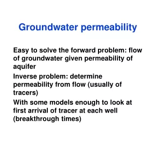
PERMEABILITY Permeability means the ease or difficulty with which water or any other liquid flow through soil. The knowledge of permeability of soil is important for the following: • Evaluating the amount of seepage through or beneath dams and levees and into water wells. • Evaluating uplift or seepage pressure beneath hydraulic structures for stability analyses. • Providing control of seepage velocities, so that, fine particles are not eroded from the soil mass. • Rate of settlement (consolidation) studies where volume changes occur as water is expelled from the voids. • Controlling seepage from sanitary landfills and hazardous liquid waste dumps. • Evaluating the yield from wells as a source of water supply. • Designing the highways sub-drainage system. • Designing sub-drainage for water logging and salinity control. • Ground water lowering (Dewatering). • Investigation of contaminated lands. • Design of landfill sites.
Soil Hydrologic Cycle Source: Vepraskas, M.J, et. Al. “ Wetland Soils”, 2001.
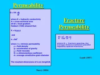
DARCY’S LAW OF FLOW THROUGH SOIL According to Darcy’s law, the velocity of flow through soil is directly proportional to the hydraulic gradient. Fig: Loss of head, due to flow of water through soil.
h=difference of head. L= length of soil between two points along the flow path Where piezometers are installed. V=velocity of flow through soil=Q/A where: Q is the discharge & A is the gross cross-sectional area of the soil i =hydraulic gradient= h/L According to Darcy’s law. V i V = ki Where K is the constant of proportionality and is known as coefficient of permeability.
Assumption of Darcy’s Law: • 1. The continuity of the flow condition in the soil mass must be satisfied with no velocity changes taking place during the flow. • 2. The flow must be with voids saturated through out the flow and no compressible air present in the voids. • The flow must be in a steady state. i.e., the velocity of flow must be constant at any particular section with respect to time. • The flow must be laminar. FECTORS EFFECTING PERMEABILITY 1. Soil grain size Permeability depends mainly on the size of voids, which in turn depends on the size, shape and state of packing of the soil particles. Permeability appears to be proportional to the square of the effective grain size. K (D10)2
For sandy soil, A.Hazen developed the following empirical equation. K = C (D10)2 cm/sec. Where, D10, is the effective grain size in centimeters. K, is coefficient of permeability in centimeters per second. C, is a constant, according to Hazen, it variesfrom about 40 to 150 expressed as 1/cm.sec. Table: Values of coefficient C for different grades of sand. Generally for sandy soil K = 100(D10)2(C.G.S. units)
2. Properties of the liquid Permeability varies with density and viscosity of fluid flowing through the soil a. Density of the fluid: K Where, = Density of fluid. b. Viscosity of the fluid: K 1/ Where: = Absolute viscosity of fluid. Since viscosity changes with temperature following equation may be used to find ‘K1’ for any temp. Where: K is co-efficient of permeability at standard temperature commonly 20 oC. K1 is the co-efficient of permeability at any test temperature. is viscosity at standard temperature i.e., 20oC. 1 is viscosity at test temperature.
3. Void ratio a. For cohesive soil – K e2 b. For non cohesive soils – K e3/1+e Cassagrande equation for fine or medium clean sand is: K = 0.85 1.4e2 K0.85 Where: K = permeability at any void ratio K0.85 = permeability at a void ratio of 0.85 4. Soil Structure Stratified soil usually has greaterpermeability in the horizontal direction than in the vertical direction. Rock/Sediment with high porosity and low permeability? 5. Degree of Saturation Increase in the degree of saturation increases permeability. K S Where, ‘S’ is degree of saturation.
6. Entrapped air within the soil Entrapped air/gases reduce the degree of saturation and permeability. Entrapped air/gases may be due to, • Chemical decomposition of soil. • Disintegration of rock and animal remains. • Dissolved air. According to D.W. Taylor the following simple Eq. relates ‘K’ to a number of factors which influence permeability. Where: DS= Effective, grain size w =Density of permeant (water/fluid) = Viscosity of permeant (water/fluid) e = Void ratio C = constant which depends on shape and arrangement of pores.
SUPERFICIAL AND SEEPAGE VELOCITY • Water moves through the soil pores. • Area of flow is actually, the cumulative pore area, which is difficult to determine. • Gross cross-sectional area of the soil cylinder is generally used for common permeability/ seepage calculations. • Velocity in this case is known as superficial velocity. • Using the area of voids, velocity is known as seepage velocity. • However for practical problems term velocity of flow is used which is based on total cross-sectional area of soil. Q = A V (where V is superficial velocity & A is the total cross- sectional area of soil) Q = Av Vs(whereVs =seepage velocity& Av =area ofvoids). Porosity= n = Vv/V For a unit thickness, n = Av/A or Av = n A Putting the value of Avin Eq. for Q., Q = n x A x Vs or n x A x Vs = A V V = n x Vs. Since n is always less than 1 therefore V < Vs.
MEASUREMENT OF PERMEABILITY Laboratory Methods • Constant head permeameter. • Variable head permeameter. First is suitable for relatively coarse grained (sandy) soils, while the second is recommended for fine grained (silty/clayey) soils. Field Method • Pumping-out test/discharge well test. • Pumping-in test/recharge well test.
CONSTANT HEAD PERMEAMETER Fig: Constant head Permeameter.
A = Cross-sectional area of soil sample L = Length of sample h = drop in head between the two piezometers l = distance between peizometers Vol. = Volume collected in time T. T = time of test According to DARCY’S law, V i V = K i Multiplying ‘A’ on both sides
In highly impervious soil, quantity of flow is small and accurate measurement of its value is not possible. Therefore the constant head permeameter is mainly applicable to relatively previous soil such as sands and gravel.
VARIABLE HEAD PERMEAMETER It is used to find the permeability of relatively less permeable soil (fine grained soil, silt and clay). it is also known as falling head permeameter.
Let a = cross-sectional area of the stand pipe. A = cross-sectional area of soil sample. L = Length of sample. h1= Initial head at time t1. h2= Final head at time t2. dh = the drop in head in time dt Velocity of fall of water level in the stand-pipe V = -dh/dt (-ve sign indicates a fall of head). Multiplying by ‘a’ on both sides V x a = - a Q = - a Q is the discharge
KAi = -a Integrating the above equation. or
FIELD DETERMINATION OF PERMEABILITY i- Discharge Well (Pumping-out Test) If water is pumped out of the test well, it is called discharge well test. The method is extensively used by water supply Engineers. In foundation engineering the important problem is the draw down of the ground water table, which is necessary to get the dry foundation pit to start the construction work. ii- Recharge Well (Pumping-in Test) When water is pumped into the well from an out side source, it is called a recharge well test. All the procedure is similar to discharge well method, except an inverted cone of depression is developed.
THEORY OF ORDINARY PERFECT WELLS (DUPUIT THIEM’S THEORY) For the derivation of an analytical equation for the discharge Q of the well or the permeability of soil K, following assumptions are made. • The soil is homogeneous, uniform and porous medium of infinite areal extent. • The well takes the ground water from the entire thickness of the permeable water bearing stratum. • There exists an unconfined, uniform, steady, laminar and radial ground water flow to the cylindrical well from a concentric boundary. • For small inclination of the free surface of the ground water gravity flow system, the streamlines can be taken as horizontal. • The horizontal velocity is independent of depth. • The hydraulic gradient is equal to the slope of the tangent at any point on the depression curve, of the free ground water table. • The coefficient of permeability K of the soil is constant at all times and at all places. • The well is being pumped continuously at a uniform rate until the flow of water to the well is stabilized.
DERIVATION OF EQUATION FOR THE CO-EFFICIENT OF PERMEABILITYITY ‘K’ a- Unconfined Aquifer: ro = Radius of the pumping well H = Thickness of water bearing stratum R = Radius of influence i.e. where the draw down S is zero x-x = Original static ground water table Smax = Maximum draw down which is at the pumping well. Upon pumping, the water table in the well lowers by an amount of S termed as draw down. The dewatered zone in the soil ABCDA takes the form of a funnel or cone known as cone of depression. The rate of flow, Q, towards the well from the surrounding soil at stabilized flow is expressed by means of Darcy’s law as follows Q = VA = Kai V = Velocity of flow A = Area of flow
Fig. Pumping test in an unconfined aquifer to find permeability
Area of flow =A= 2 x y When x = ro, y = h x = R ,y = H Integrating for the above limits.
x = r1 y = h1 x = r2 y = h2 Integrating for the above limits.
EQUATION FOR THE CONE OF DEPRESSION The curve of depressed water table Cone of depression) can be drawn, using an equation having x and y variables. x = ro, y = h x = x, y = y
Similarly the equation of depression line can be written in another form i.e. when: x = x, y = y x = R, y = H Putting different values of x in the above Equation, the corresponding values of y are calculated, then with the set of x and y co-ordinates, curve of depression line can be drawn provided K is already known. If the value of drawn down S at any point x, from the center of well (along the curve of depression) is required, the following basic equation is used.
Draw down S = H – y For pumping water out of the well (lowering of ground water table) use minus sign and for recharge of water into the well use plus sign before the square root. Maximum draw down at the pumping well can be determined by putting x = rO
YIELD OF WELL Yield of a well means, the maximum discharge capacity of the well installed in any water bearing strata. The yield depends on the permeability of water bearing strata. Yield can be determined by any of the following equations. Specific Yield The specific yield of the well, q, is defined as it’s yield per unit length (1m) of draw down in the well.
RADIUS OF INFLUENCE The radius of influence of the depression cone, R, is to be estimated from experience or it is to be determined from observation in several bore holes (observation wells) made at different distances from the test well. It can also be determined from any of the above equation, which contain the term R. According to Sichardt, for stabilized flow, R is given by an empirical equation as follows. Where: S = Maximum draw down in meters K = Coefficient of permeability of soil in m/sec. Kozeny gave an expression for the calculation of the radius of influence, R, in terms of time, t, during which yield from the well of Q (m3/sec) has been attained.