Download
1 / 18
180 likes | 232 Vues
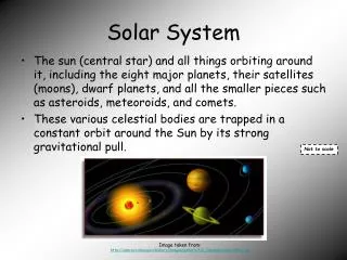
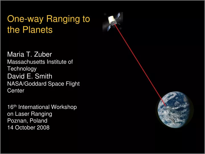
One-way Ranging to the Planets Maria T. Zuber Massachusetts Institute of Technology David E. Smith NASA/Goddard Space Flight Center 16 th International Workshop on Laser Ranging Poznan, Poland 14 October 2008. Motivation: Solar System Dynamics.

E N D
One-way Ranging to the PlanetsMaria T. Zuber Massachusetts Institute of TechnologyDavid E. SmithNASA/Goddard Space Flight Center16th International Workshop on Laser RangingPoznan, Poland14 October 2008
Motivation: Solar System Dynamics Goal to improve understanding of dynamics of solar system, its history and future evolution. This requires: • Improved knowledge of planetary orbits and locations (currently ~100 m). • Improved understanding of rotation of planets and influence of oceans, atmospheres, etc. • Planetary precession and obliquity, long- and short-term. • Orbits and locations of asteroids, particularly of Earth-orbit -crossing bodies. • Masses and motions of individual bodies in the asteroid belt, and their evolution. • Gravity field of Sun, particularly degree 2-terms (flattening and equatorial shape).
Rationale • After biases have been removed or adjusted, microwave systems routinely provide ranging to ~ 2-m over planetary distances of 2+ AU. • Obtaining cm-level precision over these distances requires optical methods. • Two-way ranging is more challenging, and riskier, although achievable. • One-way laser ranging (up to a detector, no downlink) is less accurate, but cheaper and requires less payload resources (mass, power, vol. etc.). • Stable clocks are essential; stability over time of flight (5 AU = ~2500 seconds). • BUT, it is becoming increasingly difficult to convince space agencies(at least NASA) to fly new technology, particularly lasers, on planetary missions if they have not been fully demonstrated in space and able to withstand a long cruise to destination planet.
MESSENGER Demonstration Experiment (24 M km) • Two successful demonstration experiments led to LR capability and inclusion of laser reflector array on LRO. • In late May 2005, successful ranging to to MESSENGER spacecraft and from s/c to GSFC SLR station @ 24 Mkm. • Passive scan used to verify s/c pointing and alignment. Smith et al. [2006]
MESSENGER Two-way Ranging Results • Black: Ground pulses received at MLA; 0.35 ms later than predicted. • Red: Ground received time of MLA pulses on May 27; 0.34 ms later than predicted • Blue: Ground received time of MLA pulses on May 31; ~0.14 ms earlier than predicted. • Used to derive two-way range, range rate, and acceleration at reference epoch (2005-05-27T19:46:03 UTC), as well as s/c clock offset and drift rate. Smith et al. [2006]
Solution Parameters for MESSENGER Spacecraft Smith et al. [2006]
Mars Demonstration Experiment (80 M km) • In September 2005, Mars Global Surveyor (MGS) spacecraft scanned Earth to ensure FOV of MOLA receiver would detect laser pulses. • Successfully transmitted laser pulses to MOLA on MGS s/c in Mars Orbit. MOLA laser had ceased operating in 2001 after 2.5 Earth-years of operation, but receiver continued to function. Abshire et al. [2008]
MOLA Receiver and Ground Station Parameters Abshire et al. [2008]
Pulse Counts from MOLA Receiver 28 September 2005 • Left: Channel 1 pulse count record for Scan 1, laser energy 10 mJ/pulse; 24.5 Hz average rate. • Right: Scan 2, laser energy was 11 mJ /pulse; 49 Hz average rate. • higher pulse count due to higher average pulse rate and slightly higher pulse energy. Abshire et al. [2008]
Transmit 532-nm laser pulses at 28 Hz to LRO • Time stamp departure and arrival times • Compute range to LRO Greenbelt, MD LRO LR Timeshares LOLA Detector With Lunar surface returns Receiver telescope on HGAS couples LR signal to LOLA 1/28 sec Earth Win. (8ms) Lunar Win. (5ms) Data Xfer LOLA channel 1 Detects LR signal … LR Receiver Telescope Time Fiber Optic Bundle Laser Ranging (LR) on LRO Zuber et al. [2008]
Implementation: LR combined with LOLA on LRO • Combining one-way ranging with altimeter enables same electronics to be used to time arriving pulse. • Optical receive points to ground station; accomplished by slaving optical receiver to s/c high gain antenna (HGA). • Received signal transmitted to altimeter (LOLA) by flexible fiber glass cable ~10 m in length. • LR attributes crucial for planetary missions: • no power required by optical receiver • very small mass (0.25 kg) of optical receiver LRT Upper Baffle LRT Lower Baffle Thermal Radiator High Gain Antenna Fiber Optic Connector Hole in HGA Primary Reflector LR flight unit LRO Precision Tracking Laser tracking from LR, along with LOLA and S-band will enable positional accuracies of ~25 m along track and ~0.5 m radially after improvement of lunar gravity field.
Summary • Laser ranging will provide key measurements to advance understanding of solar system dynamics. • Preliminary successes achieved: • Longest two-way laser link: Earth MESSENGER 24 Mkm [Smith et al., 2006]. • Longest one-way laser link: Earth Mars 80.1 Mkm [Abshire et al., 2008]. • First laser tracking of planetary s/c approved: Laser ranging system on Lunar Reconnaissance Orbiter [Zuber et al., 2008]. • First corner cube on planetary spacecraft: Lunar Reconnaissance Orbiter. • One-way ranging to planets represents a new frontier of laser ranging; opportunities to participate.
MGS Clock Offset • Dark green: # detected pulses in excess of those transmitted from the ground laser, versus the offset time. • Since PRT (49 Hz), was not exact multiple of MOLA counter interval (8Hz), alignment between MOLA pulse counter boundaries & transmitted pulse pattern changes with time. • Causes MOLA-detected counts from GGAO laser, in excess of those transmitted from ground, to vary with time. • Since transmitted laser pulses were gated on and off every 6 pulses, duration of each 6-pulse blanked (or off) period was 110 msec. • Count yields min, when it fits into one of 125-msec MOLA counter interval, and is aligned to it within 15 msec. • Location of this minimum in the excess count (black arrow) gives a new estimate between the ground station times (UTC) and MOLA counter times. • Since these are tied to the MGS clock, improved estimate of offset of MGS clock results. Time record of MOLA-detected excess pulse count for scan 1, with laser was gated by shutter, with transmitted pulse pattern plus light travel time from Earth to MOLA. Abshire et al. [2008]
Abstract Often the increase in mission complexity of flying an active laser system to the planets limits the opportunities for attempting laser tracking of planetary spacecraft. The best and most accurate method is generally considered to be the transponder approach that involves active laser systems at both ends of the link. But because of the increased complexity, risk and cost of a two-way system we have been forced to consider the value of a one-way measurement in which most of the complexity and costs are at the Earth terminal, and therefore more palatable and “fixable’ should issues arise. This was the choice for LRO and hence the development of the LR system which was minimal in cost and required almost no additional spacecraft resources. The advantage of “one-way” is clear for distances of several AU if the issues of precision versus accuracy can be resolved and the opportunities for flight are greater.
MESSENGER Demonstration Experiment (24 M km) • We recently performed 2 successful demonstration experiments that have led to LR capability on LRO, and inclusion of laser reflector array on s/c. • In late May 2005 we successfully ranged up to the MESSENGER spacecraft and also from s/c to GSFC SLR station @ 24 Mkm. • Black: Ground pulses received at MLA; 0.35 ms later than predicted. • Red: Ground received time of MLA pulses on May 27; 0.34 ms later than predicted • Blue: Ground received time of MLA pulses on May 31; ~0.14 ms earlier than predicted. • Used to derive two-way range, range rate, and acceleration at reference epoch (2005-05-27T19:46:03 UTC), as well as s/c clock offset and drift rate. Smith et al. [2006]
Ideas: Done - MLA expt., MOLA expt., LOLA and LR Range: typical 2AU but 5 AU for Europa Power on the ground; receiver on s/c Glass fiber cables Mass, complexity Reasons why we want optical Timing systems Calibration of clock differences on orbit Radiometry