Download
1 / 43
450 likes | 626 Vues
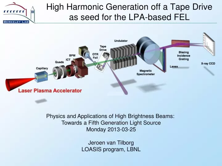
High Harmonic Generation off a Tape Drive as seed for the LPA-based FEL. Physics and Applications of High Brightness Beams: Towards a Fifth Generation Light Source Monday 2013-03-25 Jeroen van Tilborg LOASIS program, LBNL. Acknowledgements.

E N D
High Harmonic Generation off a Tape Drive as seed for the LPA-based FEL Physics and Applications of High Brightness Beams: Towards a Fifth Generation Light Source Monday 2013-03-25 Jeroen van Tilborg LOASIS program, LBNL
Acknowledgements HHG experiments: Brian Shaw, Thomas Sokollik, Jeroen van Tilborg, and Wim Leemans FEL concept & simulations: Carl Schroeder Other LOASIS contributors: Sergey Rykovanov, Anthony Gonsalves, Kei Nakamura, Sven Steiniger, Nicholas Matlis, Eric Esarey, Csaba Tóth, Carlo Benedetti, and Cameron Geddes Collaborators CEA Saclay: Sylvain Monchocé, Fabien Quéré, Arnaud Malvache, and Philip Martin LBNL, ALS: Eric Gullikson LBNL, Metrology: Valeriy Yashchuk, Wayne McKinney, and Nikolay Artemiev LDRD
Outline • Efforts at LOASIS/Bella • Introduction to Coherent Wake Emission • Experimental setup and data • Influence of tape and laser parameters • FEL calculations • Comparison CWE details to model
Each LOASIS/Bella system addresses unique challenges Matlis, 10:50am Measured at LOASIS High-quality LPA e-beams: compact coherent light source [energy, stability1, emittance2, (slice) spread3, charge] • 1. Jet+Cap, Gonsalves et al. Nat. Phys 7 (2011) • 2. Betatron X-rays: Plateau et al. PRL 109 (2012) • 3. COTR: Lin et al. PRL 108 (2012) Godzilla TREX Bella Plateau et al. PRL 109 (2012) Gonsalves et al. Nat. Phys 7 (2011)
Seeding the FEL has benefitsGoal: 53-nm LPA-driven seeded FEL Schroeder et al., Proc. FEL (2006) Schroeder et al., Proc. FEL (2008)
High-power lasers: trade-off scale-length and HHG divergence gas-based HHG Large spot (small HHG divergence) 200 mJ Laser ROM HHG Small spot (large HHG divergence) • Coherent Wake Emission • I~1x10¹⁷ W/cm2 • <2 meter delivery optics • Target destruction: tape! • Combiner, no transport • Easy spatial overlap • Quasi-linear regime
Step 1 & 2: Electrons are pulled out of plasma into vacuum, and back into target Heissler et al. Appl. Phys. B 101 (2010) • Step 1 • Laser 45o on high-n target • Ionization • Brunel electrons into vacuum • Step 2 • Restoring force turns electrons around into target • “Ejection phase” determines return time and return velocity • E-beam chirp leads to bunching Hörlein, thesis MPQ (2008)
Step 3: Electron beamlets drive wake and emit radiation at density step electron beam Plasma ωp • At density step, e-beam creates plasma wave • Light emitted at plasma frequency • Gradient density emits broad spectrum • Maximum frequency given by maximum density • Every cycle Even and odd harmonics • Atto-chirp present (high frequencies late)
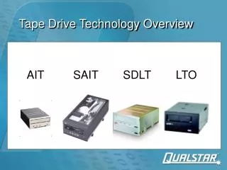
Experimental Setup Borot et al. Opt. Lett. 36 (2011) • Focal length=2m, θ=35 mrad (FWHM) • P-polarization after 3” waveplate • Change energy, zfocus, compression • Mylar, VHS, Kapton tape. Glass plate • Silicon Brewster plate (X~100) • 100-nm-period transmission grating • Double-stacked MCP
Orders up the 18th observed,at divergences of 4-15 mrad Shaw et al., submitted Al foil Table from Queré (CEA Saclay)
Dependence spectrum on intensity • VHS tape (“front”, iron oxide side) • 15th and 16th only at higher intensities • 15th harmonic, x225 over-critical • Lower intensity density not high enough 70 mJ 150 mJ 300 mJ 15th 15th 150 mJ 70 mJ 15th
Divergence depends on tape material Same laser conditions different targets different divergences Glass 3.9 mrad (rms) Kapton 7.4 mrad (rms) VHS & Mylar ~13 mrad (rms) Roughness plays role?
Roughness more complex than just “sigma” Harvey et al. Opt. Eng. 51 (2012) 1/λ 1/w0 Metrology ALS reflectometry k Gold 627x470 μm Kapton 627x470 μm 20 μm 20 μm Power Spectral Density ~ FFT[ height distribution ]
Metrology reveals differences in roughness(correlated to divergence) Glass 3.9 mrad (rms) Kapton 7.4 mrad (rms) VHS & Mylar ~13 mrad (rms)
Quasi-linear CWE provides stability VHS-front (iron-oxide on Mylar) 30 mrad • Pointing fluctuation • 0.2 mrad • Divergence • fluctuation • 2 mrad • Fluctuations total counts ~5%
Concave reflective grating order-specific divergence VHS-front (iron-oxide on Mylar) Integrated over entire spectrum 33 mrad (FWHM) 13th 14th 15th 11.5 mrad (FWHM) 17 mrad (FWHM) 15 mrad (FWHM)
Absolute flux calibration: megaWatts seed in 15th order ALS CXRO beamline 6.3.2 (http://cxro.lbl.gov/reflectometer) • Flux • Circa 20% in 15th order • 67 photons/count, 5x10⁹ photons, 20 nJ • Lose 40% Al foil, • 35% Brewster plate • 50 nJ in 20 fs, is ~2.5 MW • Laser energy on target ~ 70 mJ • CE for 15th is 7x10⁻⁷ • Up to 250 mJ available • Working on improvement Borot et al. Opt. Lett. 36 (2011) CWE Easter et al. Opt. Lett. 35 (2010)
Measured seed parameters & FEL model predict FEL gain Seed: 15th harmonic 60 nJ in 20 fs Focus 1 cm upstream Divergence 5.7 mrad (rms) 100 nJ Seed strength as Undulator & e-beam: 4.4 kA peak current 25 micron transverse size Undulator period 2.18 cm K=1.25 Wavelength 53 nm (15th) Pierce parameter 0.012 2 mrad 5 mrad 10 mrad 15 mrad Z [m] Model: Mono-energetic e-beam 1d FEL radiation Not included: slippage, wavefront curvature Shaw et al., submitted Phase electron Energy electron FEL radiation
Further seed source improvement possible? Spectral details give insight 70 mJ 150 mJ 300 mJ 15th 15th 150 mJ 70 mJ 15th
Concentrate on 12th harmonic: higher intensity broadening & blue-shifting 70 mJ 150 mJ Focal scans Always a red-shifted spectrum Higher intensity Broadening Higher intensity Less red-shifting 70 mJ 150 mJ Energy scan driver 800nm order 820nm/q 300 mJ
Use of a model to predict attochirp: dependent on intensity and density gradient Density n(x) Longer gradient longer delay Higher a faster e’s shorter delay Leading edge: next cycle emits faster then previous one blue-shifting Harmonic q Malvache et al., PRE 87 (2013) nc,ωq Fundamental nc,ωL xω x x=0
Energy and Focal scans: Model incomplete to match data • No red-shifting • Higher intensity • Narrowing • No shifts 150 mJ Focal scan Energy scan • Model • No averaging over spot-size • No propagation to diagnostic van Tilborg et al., in preparation (LBNL) 70 mJ • Red-shifting • Higher intensity • Broadening • Less red-shifting 150 mJ Energy scan Focal scan 300 mJ
Expand the model: include expanding plasma gradient Increasing gradient length δ (distance ncr to ncr,q) Density n(x) nmax Warm plasma nq Harmonic q • Plasma expansion • Saclay*: Pump 1e15 W/cm2 Cs=20 nm/ps • We: Pump 3e17 W/cm2 Cs~100-1000 nm/ps nc,ωq Heissler et al., Appl. Phys. B 101 (2010) Brunel orbits Fundamental nc,ωL xω x x=0
Energy and Focal scans: better agreement expanded model • Red-shifting • Higher intensity • Broadening • Less red-shifting 150 mJ Energy scan Focal scan 70 mJ • Red-shifting • Higher intensity • Broadening • Less red-shifting 150 mJ Energy scan Focal scan 300 mJ
Conclusion • Research towards compact (seeded) LPA-based FEL • HHG from spooling tape • Harmonics up to the 17th, 5-15 mrad divergence • Tape roughness at micron-level is relevant • MW-powers from VHS and Kapton • FEL model predicts seed-induced bunching • CWE model suggests plasma expansion relevant • New round of CWE experiments planned
ALS data reveals <13 nm on most samples(weak correlation divergence) ALS reflectometry 1/λ 1/w0 k Glass 3.9 mrad (rms) Kapton 7.4 mrad (rms) VHS & Mylar ~13 mrad (rms)
Laser chirp can compensate for CWE femtochirp ξ=1 (red front) ξ=-1 (blue front) ξ=0 Borot et al. Opt. Lett. 36 (2011) Blue-shifting Red-shifting
Stable shot to shot performance Experiment Experiment Scan parameter Model • Comparison Experiment to Model • Insight in CWE physics • Use insight for optimization Scan parameter
Questions • Sergey, what drives the electrons back into the target. The laser, or the restoring force of the plasma? If a density gradient exists, which electrons get pulled out? Where is the field supposed to be zero? Where does density gradient come from? Surface roughness? Plasma expansion into vacuum? • Thomas Strehl Ratio e-beam Tape Drive HHG drive laser
Bottom line: deliver seed strength 10-6-10-5 to undulator Seed: 60 nJ in 20 fs Model: 1d-description FEL radiation No wavefront effects No slippage 100 nJ Seed strength as 2 mrad 5 mrad 10 mrad 15 mrad 2 nJ 2 mrad Z [m] Phase electron Energy electron FEL radiation
Notes on Sequoia Scan Divergence 4-15 mrad (rms)
Notes on Compressor Data -In-vacuum optimum compression is at comp4=-0.1mm. -Positive Comp4 Negative xi Blue front, red back Makes femtochirp worse Broad harmonics -Scan 33 on 2012-07-09 (CWE day 2). Transmission through Kapton (on fiber Hamamatsu). -Reflectometry on 2012-10-04 scan (VHS-front) Chromax -Also confirmed by 2012-06-28 (CWE day 1), compressor scan Sequoia data and Grenouille data where taken and compared on 2012-09-05. By including temporal resolution, nice fitting for both diagnostics is retrieved Scan33, 2012-07-09
Notes on spot size -In-vacuum smallest spot is at z=+2 mm -Positive z focus downstream (more harmonics if focused at z=2mm, but smaller divergence at z=>3mm, see Day 2, scan 20) -Guppy scan on 2012-06-26 (scan 16) gives a FWHM at focus of 23 micron. -Guppy Strehl ratio experiments on 2012-07-18 give a FWHM of 23 micron (w0=19.5 micron), and a Strehl ratio of 0.73. -Use file “NotesSpotAveragedIntensity”. Based on 73%, we calculate a 100 mJ, 47.7 fs (I-FWHM), we find an Ipeak of 2.04e17 Wcm2. -We fitted the max-counts versus z to calculated intensity at other z’s. 2012096026, scan 16
Roughness more complex than just “sigma” FFT[ h(x) ] FFT[ h(x) ] Same Sigma, Different regime Critical is the spatial frequencies 1/λ k [nm-1] Assumption Nevot-Croce “single σ“ CXRO grazing reflectometry λ λ 1/λ k [nm-1]
Conclusion Gradient length δ Function 1 Vdelta=1e-5 Time shift = 1e-5 ps per cycle, or 3nm per cycle, or 1100 nm/ps
e- beam laser Intro to Laser Plasma Accelerators (LPA’s) LPA: Self injection + acceleration Godzilla TREX Bella
High-power lasers: trade-off scale-length and HHG divergence • General concept: More laser More harmonics • Example, 200 mJ of laser, 50 fs • Gas-based harmonics • Requirement: I~5x10¹⁴ W/cm2 • Yields spotsize w0=0.7 mm, zR=1.9 m • At z=5 m: w0=1.9 mm, Fluence=1900 mJ/cm2 • At z=10 m: w0=3.7 mm, Fluence= 470 mJ/cm2 • ROM harmonics • Requirement: I~1x10¹⁹ W/cm2 • Yields spotsize w0=5 μm, zR=100 μm, θ=50 mrad • Typically: Divergence harmonics ~ divergence laser • Coherent Wakefield Emission • Intensities around I~1x10¹⁷ W/cm2 • <20-mrad laser divergence • <2 meter delivery optics • CHALLENGE: Target destroyed every shot!
Intensity regimes for Laser-produced Harmonics • Gas-based HHG • Intensity ~ Ionization potential • Laser on underdense plasma • Phase matching (along z) important • Reflection off “relativistic mirror” • Laser on overdense plasma • a0>>1: longitudinal quiver motion • Coherent Wakefield Emission • Laser on overdense plasma • Quasi-linear motion of surface electrons
Laser chirp can compensate for CWE femtochirp Blue-shifting Red-shifting ξ=-1 (blue front) ξ=1 (red front Borot et al. Opt. Lett. 36 (2011)
Coherent Wakefield Excitation: 3-step model for laser-plasma interaction Heissler et al. Appl. Phys. B 101 (2010) • Laser (p-polarized) drives surface electrons out-of-target • Laser & plasma restoring force drive electrons back. • E-bunches travel through density gradient, emit radiation at the plasma frequency
FEL simulation based on CWE source • Seed • 50 nJ in the 15th • 7 mrad (rms) divergence • Source 1 cm from undulator • 20 fs (FWHM duration) • Electron beam • 307 MeV, λu=53 nm (15th) • 25 pC (5 fs flat-top from LPA) • Transverse size ~20 micron • Ideal 0.5% dE/E, upto 4% dE/E • Include beam decompression Energy Decompression • Undulator • Six 22-period sections (now three) • K=1.25 Time • Comments • Optimize simulations • Tapered undulator help • Have energy up to 200 mJ available • Seen 5-mrad (rms) divergence on VHS (Int) • Kapton, integrated ~50% of VHS (Int) • Optimization underway no decompression seeded FEL x10 decompression seeded FEL
Repeats every laser cycle: odd and even harmonics • In a density ramp: • Consider all n’s, each at specific location x • Emission of continuous spectrum • Low frequencies emitted first Attochirp • Happens every cycle: Even & odd harmonics Hörlein, thesis MPQ (2008) tL=2.67 fs