Download

1 / 20
200 likes | 202 Vues
Micromegas TPC studies at high magnetic fields using the charge dispersion signal. D. Attié , A. Bellerive, K. Boudjemline, P. Colas, M. Dixit, A. Giganon, I. Giomataris, V. Lepeltier, S. Liu, J.-P. Martin, K. Sachs, Y. Shin and S. Turnbull

E N D
Micromegas TPC studies at high magnetic fields using the charge dispersion signal D. Attié, A. Bellerive, K. Boudjemline, P. Colas, M. Dixit, A. Giganon, I. Giomataris, V. Lepeltier, S. Liu, J.-P. Martin, K. Sachs, Y. Shin and S. Turnbull COSMo (Carleton, Orsay, Saclay, Montreal) Collaboration 11th Vienna Conference on Instrumentation – February 27, 2007
Expectations for ILC-TPC • The Time Projection Chamber (TPC) for the International Linear Collider (ILC) will need to measure about 200 track points with a transverse resolution close to 100 µm. • Pad width of 2 mm provides good two-track separation. With the choice of 2 mm x 6 mm pads, the ILC-TPC will have ~ 1.2 × 10⁶ channels. • But is still too wide to give the target resolution (s0 ~ pitch/√12). • Not enough charge sharing, even for 1 mm pitch pads (in the case of Micromegas: s avalanche ~ 12 µm) • Pads narrower than 1 mm are needed. This has consequences on: • Electronic cost • Material budget • Cooling aspects 11th Vienna Conference on Instrumentation – February 27, 2007
Solution: use a charge dispersion signal Simulation Data • Disperse the signal sharing the charge between several neighbouring pads after amplification, using a resistive coating on an insulator • The charge arrives on the central pad • and is spread over the others pads which • see a fraction of the charge after a delay • Then we fit the signal over the pads which • gives us the track position 2 x 6 mm2 pads M.S.Dixit and A. Rankin NIM A566 (2006) 281 11th Vienna Conference on Instrumentation – February 27, 2007
Micromegas: gas amplification system • Micromegas is a parallel plate gas avalanche detector with a small gap • Micromesh held by pillars 50 m above the anode plane Charge particle Drift electrode Edrift = 100-1kV/cm Conversion gap > 3 mm Amplification gap ~ 50 mm Micromesh ― Pillars ― Eamp = 50k-100 kV/cm Pads 11th Vienna Conference on Instrumentation – February 27, 2007
Charge dispersion in a MPGD with a resistive anode • 2D Telegraph equation: • Modified MPGD anode with a high resistivity film bonded to a readout plane with an insulating spacer • Point charge at r = 0 & t = 0 disperses with time • The charge density r(r,t) at (r,t) is a solution of the 2D Telegraph equation • The anode charge density is time dependent and sampled by readout pads Q(t) (r) mesh resistive foil glue pads (r,t) integral over pads PCB M.S.Dixit et.al., NIM A518 (2004) 721 r (mm) t (ns) 11th Vienna Conference on Instrumentation – February 27, 2007
Charge dispersion in a MPGD with a resistive anode • 25 µm mylar with Cermet (Al-Si) of 1 MW/□ glued onto the pads with 50 µm thick dry adhesive • The Cermet is a composite material composed of ceramic and metallic materials Al-Si Cermet on mylar Drift Gap MESH Amplification Gap Micromegas detector + resistive anode 11th Vienna Conference on Instrumentation – February 27, 2007
Micromegas gain • The resistive foil prevents charge accumulation, thus prevents sparks • Gains higher than obtained with standard anodes can be reached ― Without resistive foil ― With resistive foil (current) ArIso5% 11th Vienna Conference on Instrumentation – February 27, 2007
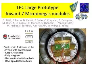
The 5 T cosmic-ray test at DESY • Carleton TPC + 10 x 10 cm2Micromegas (50 mm gap) + resistive anode • 128 pads:- 126 tracking pads (2 x 6 mm2) in 7 rows - 2 trigger pads (36 x 6 mm2) in 2 rows • Drift length: 15.7 cm • Aleph charge preamplifiers + 200 MHz FADCs digitizer 11th Vienna Conference on Instrumentation – February 27, 2007
The 5 T cosmic-ray test at DESY • 4 weeks of data using the 5 T magnet (thanks to DESY and T. Behnke et al.) • 2 gas mixtures used: - Ar+5% isobutane: easy gas, for reference - Ar+3% CF4+2% isobutane: • ·so-called T2K gas, • ·good trade-off for safety, · high velocity (7.2 cm/ms at 200 V/cm), • ·low longitudinal diffusion, • ·large wt ~ 20 at 5 T ie DTr = 19 mm/√cm. • Most data taken- at 5 T (to limit the diffusion) and - at 0.5 T (low enough field to check the effect of diffusion) • 55Fe source used for gain measurements • placed inside the chamber 11th Vienna Conference on Instrumentation – February 27, 2007
Gain dependence on magnetic field Micromegas gain vs. magnetic field with a 55Fe source for Ar+5%C4H10 Gain relative to B = 1T Magnetic field (T) Micromegas gain constant to within ~ 0.5 % up to 5 Tesla ! 11th Vienna Conference on Instrumentation – February 27, 2007
Cosmic-ray data taken at DESY 2 mm 6 mm Sample cosmic ray tracks B = 0.5 T 11th Vienna Conference on Instrumentation – February 27, 2007
Charge dispersion pulses & pad response function • The Pad Response Function (PRF) is a measure of signal size as a function of track position relative to the pad. • The pulse shape is variable and non-standard because of • both the rise time & pulse amplitude depend on track position. • The PRF amplitude for longer drift distances is lower due to Z dependent normalization. 11th Vienna Conference on Instrumentation – February 27, 2007
Parameterization of the PRFs • The PRFs are not Gaussian. • The PRF depends on track position relative to the pad: PRF = PRF(x,z). • PRFs determined from the data and parameterized by a ratio of two symmetric 4th order polynomials: • a2, a4, b2 & b4 can be written down in terms of: • - FWHM =(z) • - base width (z) of the PRF. Amplitude The parameters depend on TPC gas and operational details x/mm 11th Vienna Conference on Instrumentation – February 27, 2007
Track fit using the PRF y f 6 mm x x0 2 mm • For a given track: xtrack= x0 + tan() yrow • Yrow is the y position of the row and x0 & the track fitting parameters • Determination of x0 & by fitting the PRF to the pad amplitude by minimizing2 for the entire event • Definitions of the different stages: • - residual: xrow-xtrack • - bias: mean of residual xrow-xtrack = f(xtrack) • - resolution: geometric mean of the standard • deviations of track residuals 11th Vienna Conference on Instrumentation – February 27, 2007
Pad Response Function (PRF) 0 < z < 1 cm 1 < z < 2 cm 2 < z < 3 cm 4 < z < 5 cm 3 < z < 4 cm normalized amplitude • T2K gas • B = 5 T • 15 z regions / 1 cm step 5 < z < 6 cm 6 < z < 7 cm 7 < z < 8 cm 9 < z < 10 cm 8 < z < 9 cm 10 < z < 11 cm 11 < z < 12 cm 12 < z < 13 cm 14 < z < 15 cm 13 < z < 14 cm xtrack – xpad (mm) 4 pads / ±4 mm 11th Vienna Conference on Instrumentation – February 27, 2007
Residuals: xrow-xtrack 2 < z < 3 cm 0 < z < 1 cm 1 < z < 2 cm 14 < z < 15 cm 13 < z < 14 cm 12 < z < 13 cm 11th Vienna Conference on Instrumentation – February 27, 2007
Average residual vs x position (± 0.15 mm) (± 14 mm) • A bias of up 100 mm is observed attributed to the charge spread non-uniformity due to: - inhomogeneities in the gap size - non-uniformity of the foil resistivity correction bias after bias before row 1 ± 20 mm row 2 row 3 11th Vienna Conference on Instrumentation – February 27, 2007
Resolution at 0.5T vs. gain • B = 0.5 T, resolution fit by where • Resolution 0( at z = 0) ~50 µm still good at low gain (will minimize ion feedback) • Mean of Neff = 27 (value measured before ~ 22) s0 = 1/40 of pad pitch Gain = 4700 Gain = 2500 Neff=25.2±2.1 Neff=28.8±2.2 11th Vienna Conference on Instrumentation – February 27, 2007
Resolution at 5T vs. gas mixtures Ar Iso (95:5) B = 5T Extrapolate to B = 4T with T2K gas for 2x6 mm2 pads: • DTr = 23.3 µm/cm, • Neff ~ 27, • 2 m drift distance, Resolution of Tr 80 m will be possible !!! • Analysis: - Curved track fit • - EP < 2 GeV • - |f| < 0.05 (~3°) ~ 50 µm independent of the drift distance 50 mm 11th Vienna Conference on Instrumentation – February 27, 2007
Conclusions • Micromegas with a resistive anode has been successfully operated in a 5 T magnetic field. • s ~ 50 mover 15 cm (transverse diffusion negligible) extrapolates to 80 m at 2 meters. • The Ar+3% CF4+2% Isobutane gas mixture is promising. • Can be also used with bulk technology for T2K experiment (See A. Sarrat’s poster A22). 11th Vienna Conference on Instrumentation – February 27, 2007