Download
1 / 58
590 likes | 757 Vues
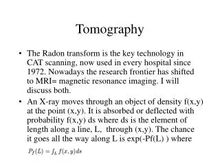
Network Tomography. CS 552 Richard Martin. What is Network Tomography?. Derive internal state of the network from: external measurements (probes) Some knowledge about networks Captured in simple models. Why Perform Network Tomography?. Can’t always see what’s going in the network!

E N D
Network Tomography CS 552 Richard Martin
What is Network Tomography? • Derive internal state of the network from: • external measurements (probes) • Some knowledge about networks • Captured in simple models.
Why Perform Network Tomography? • Can’t always see what’s going in the network! • Vs. direct measurement. • Performance • Find bottlenecks, link characteristics • Diagnosis • Find when something is broken/slow. • Security. • How to know someone added a hub/sniffer?
This week’s papers • J. C. Bolot • Finds bottleneck link bandwidth, average packet sizes using simple probes and analysis. • R. Castro, et al. • Overview of Tomography Techniques • M. Coats et. al. • Tries to derive topological structure of the network from probe measurements. • Tries to find the “most likely” structure from sets of delay measurements. • Heidemann et. Al. • Recent survey and techniques (as of summer 2008)
Measurement Strategy • Send stream of UDP packets (probes) to a target at regular intervals (every d ms) • Target host echos packets to source • Size of the packet is constant (32 bytes) • Vary d (8,20,50, 100,200, 500 ms) • Measure Round Trip Time (RTT) of each packet.
Definitions sn sending time of probe n rn: receiving time of probe n rttn = rn -sn: probe’s RTT d: interval between probe sends Lost packets: rn undefined, define rttn =0.
Time Series Analysis Min RTT: 140 ms Mean RTT: ? Loss rate: 9% RTTn (ms) n (packet #)
Classic Time series analysis • Stochastic analysis • View RTT as a function of time (I.e. RTT as F(t)) • Model fitting • Model prediction • What do we really want from out data? • Tomography: learn critical aspects of the network
Phase Plot: Novel Interpretation RTTn+1 RTTn View difference between RTT’s, not the RTT itself Structure of phase plot tells us: bandwidth of bottleneck!
m Simple Model Fixed delay Variable delay Probe Traffic D FIFO queue rttn = D + wn + p/m Other Internet traffic m: bottleneck router’s service rate k: buffer size p: size of the probe packet (bits)wn: waiting time for probe packet n
Expectation for light traffic • What do we expect to see in the phase plot • when traffic is light • d is large enough and p small enough not to cause load. • wn+1 = wn • rttn+1 = rttn • For small p, approximate wn = 0
Light Traffic Example n=800 d=50 ms RTTn+1 (ms) “corner” (D,D) D = 140 ms RTTn (ms)
m Heavy load expectation FIFO queue Probe Traffic D Pn+k Pn+1 Pn+2 Burst Pn rttn+1 = rttn + B/m Probe compression effect rttn+2 - rttn+1 = (rn+2 - sn+2 ) - (rn+1 - sn+1) = (rn+2 - rn+1 ) - (sn+2 - sn+1) = p/m - d Time between probe sends Time between compressed probes
Heavy load, cont/ • What does the entire burst look like? rttn+3 - rttn+2 = rttn+k - rttn+k-1 = p/m - d • Rewrite: rttn+1 = rttn + (p/m - d) • General form: y= x+ (p/m - d) Should observe such a line in the phase plot.
Finding the bottleneck Find intercept. Know p, d, can compute m ! y= x+ (p/m - d) d
Average packet size • Can use phase data to find the average packet size on the internet. • Idea: large packets disrupt phase data • Disruption from constant stream d, can infer size of the disruption. • Use distribution of rtt’s
Average packet size • Lindley’s Recurrence equation • Relationship between the waiting time of two successive customers in a queue: wn: waiting time for customer n yn: service time for customer n xn: interarrival time between customers n, n+1 n n+1 xn time arrivals yn wn n n-1 departures wn+1 wn+1= prev. packet wait + service - overlap wn+1= wn + yn -xn, if wn + yn -xn > 0
Finding the burst size • Model a slotted time of arrival where slots are defined by probe boundaries wbn= max(wn + p/m, 0) • Apply recurrence: wn+1= wn + (p +bn)/m - d • Substitute and solve for bn: Note: assume wn + (p +bn)/m - d > 0, then bn= m(wn+1 - wn + d) - p
Distribution plot 1st peak wn+1-wn = p/m-d 2nd: wn+1=wn 3rd: bn= m(wn+1-wn+d)-p know, m, d, p solve for bn distribution of wn+1 - wn + d, d = 20 ms
Inter-arrival times • A packet arrived in a slot if: wn+1- wn > p /m - d • Choose a small d • Avoid false positives • Count a packet arrival if: wn+1- wn >0
Fraction of arrival slots Fitted to p(1-p)k-1, p=0.37 slot
Packet loss • What is unconditional likelihood of loss? • ulp = P(rttn=0) • Given a lost packet, what is conditional likelihood will lose the next one? • clp = P(rttn+1=0 | rttn=0 ) • Packet loss gap: • The number of packets lost in a burst • plg = 1/(1-clp)
Tomography Overview • Basic idea • Methods • Formal analysis • Future directions
Traffic Matrix Approaches • Cast problem of the form: • Yt= Axt+et
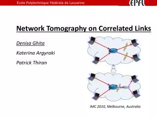
Traffic Matrix example • Send multicast packet • Measure delay of packet at receivers • Shared paths result in shared delay • Find the “most likely” tree given the observations
Traffic Matrix Example Source node Intermediate routes Destination nodes
Problem Set-up Y A X End observed delay Routing matrix Link delays
Introduction • Performance optimization of high-end applications • Spatially localized information about network performance • Two gathering approaches: • Internal: impractical(CPU load, scalability, administration…) • External: network tomography • Cooperative conditions: increasingly uncommon • Assumption: the routers from the sender to the receiver are fixed during the measurement period
Contributions • A novel measurement scheme based on special-purpose unicast “”sandwich” probes • Only delay differences are measured, clock synchronization is not required • A new, penalized likelihood framework for topology identification • A special Markov Chain Monte Carlo (MCMC) procedure that efficiently searches the space of topologies
Sandwich Probe Measurements • Sandwich: two small packets destined for one receiver separated by a larger packet destined for another receiver
Sandwich Probe Measurements • Three steps • End-to-end measurements are made • A set of metrics are estimated based on the measurements • Network topology is estimated by an inference algorithm based on the metric
Step 1: Measuring (Continue) • Each time a pair of receivers are selected • Unicast is used to send packets to receivers • Two small packets are sent to one of the two receivers • A larger packet separates the two small ones and is sent to the other receiver • The difference between the starting times of the two small packets should be large enough to make sure that the second one arrives the receiver after the first one • Cross-traffic has a zero-mean effect on the measurements (d is large enough)
Step 1: Measuring (Continued) • g35 is resulted from the queuing delay on the shared path
Step 1: Measuring (Continued) • More shared queues larger g : g34 > g35
Step 2: Metric Estimation • More measurements, more reliable the logical topology identification is. • The choice of metric affects how fast the percentage of successful identification improves as the number of measurements increases • Metrics should make every measurement as informative as possible • Mean Delay Differences are used as metrics • Measured locally • No need for global clock synchronization
Step 2: Metric Estimation(Continued) • The difference between the arrival times of the two small packets at the receiver is related to the bandwidth on the portion of the path shared with the other receiver • A metric estimation is generated for each pair of receivers.
Step 2: Metric Estimation(Continued) • Formalization of end-to-end metric construction • N receivers N(N-1) different types of measurements • K measurements, independent and identically distributed • δ(k) – difference between arrival times of the 2 small packets in the kth measurement • Get the sample mean and sample variance of the measurement for each pair (i,j): xi,j and si,j2 (Sample mean of sample X = (X1, X2, ...) is Mn(X) = (X1 + X2 + ··· + Xn) / n (arithmetic mean) Sample variance is (1 / n)Σi=1..n (Xi − μ)2 E(Mn) = μ )
Step 3: Topology Estimation • Assumption: tree-structured graph • Logical links • Maximum likelihood criterion: • find the true topology tree T* out of the possible trees (forest) F based on x • Note: other ways to find trees based on common delay differences (follow references) • Probability model for delay difference • Central Limit Theoremxi,j ~ N(γi,j ,σi.j/n i,j) • yi,j is thethe theoretical value of xi,j • That is, sample mean be approximately normally distributed with mean yi,jand variance si.j/n i,j • The larger n i,j is, the better the approximation is.
Step 3: Topology Estimation(Cont.) • Probability density of x is p(x|T, m(T)), means m(T) is computed from the measurements x • Maximum Likelihood Estimator (MLE) estimates the value of m(T) that maximizes p(x|T, m(T)), that is, • Log likelihood of T is • Maximum Likelihood Tree (MLT) T* T* = argmax TЄF
Step 3: Topology Estimation(Cont.) • Over fitting problem: the more degrees of freedom in a model, the more closely the model can fit the data • Penalized likelihood criteria: • Tradeoff between fitting the data and controlling the number of links in the tree • Maximum Penalized Likelihood Tree(MPLT) is
Finding the Tallest Tree in the Forest • When N is large, it is infeasible to exhaustively compute the penalized likelihood value of each tree in F. • A better way is concentrating on a small set of likely trees • Given: • Posterior density = x can be used as a guide for searching F. • Posterior density is peaked near highly likely trees, so stochastic search focuses the exploration
Stochastic Search Methodology • Reversible Jump Markov Chain Monte Carlo • Target distribution: • Basic idea: simulate an ergodic markov chain whose samples are asymptotically distributed according to the target distribution • Transition kernel: transition probability from one state to another • Moves: birth step, death step and m-step
Birth Step • A new node l* is added extra parameter ml* • The dimension of the model is increased • Transformation (non-deterministic) ml* = r x min(mc(l,1), mc(l,2)) m’c(l,1) = mc(l,1) – ml* m’c(l,2) = mc(l,2) - ml*
Death Step • A node l* is deleted • The dimension of the model is reduced by 1 • Transformation (deterministic) mc(l,1) = m’c(l,1) + ml* mc(l,2) = m’c(l,2) + ml*
m –step • Choose a link l and change the value of ml • New value of ml is drawn from the conditional posterior distribution
The Algorithm • Choose a starting state s0 • Propose a move to another state s1 • Probability = • Repeat these two steps and evaluate the log-likelihood of each encountered tree • Why restart?
Penalty parameter • Penalty = 1/2log2N • N: number of receivers
Simulation Experiments • Compare the performance of DBT(Deterministic Binary Tree) and MPLT • Penalty = 0 (both will produce binary trees) • 50 probes for each pair in one experiment, 1000 independent experiments • When the variability of the delay difference measurements differ on different links, MPLT performs better than DBT • Maximum Likelihood criteria can provide significantly better identification results than DBT