Download
1 / 30
400 likes | 1.53k Vues
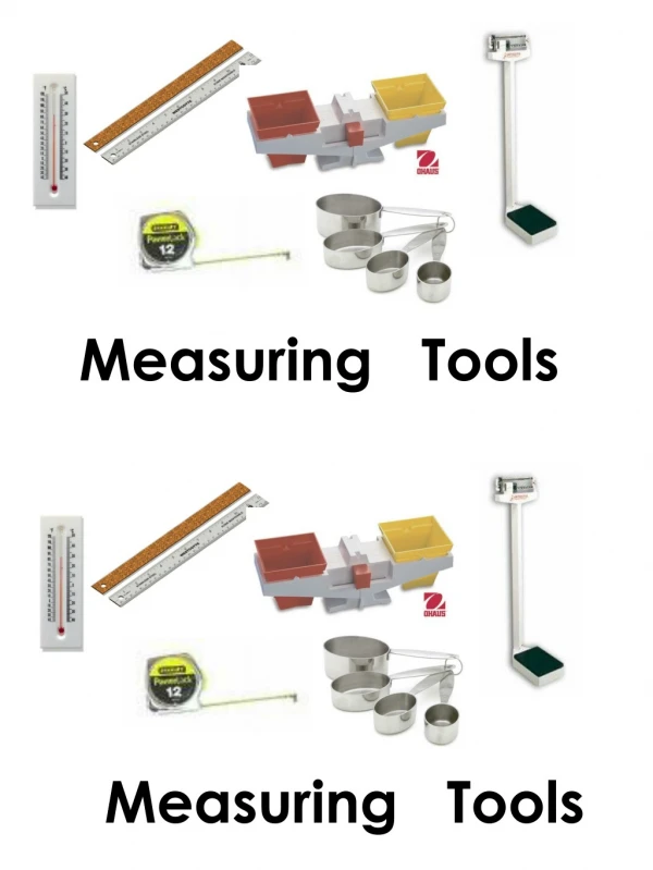
Measuring Tools. Introduction. Measuring tools for small engines are divided into three categories. Direct reading Measurement transferring Reject gages. Direct Reading Measuring Tools. Small engines use two types of direct reading measuring tools: Micrometers Calipers. Micrometers.

E N D
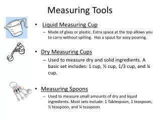
Introduction Measuring tools for small engines are divided into three categories. • Direct reading • Measurement transferring • Reject gages
Direct Reading Measuring Tools Small engines use two types of direct reading measuring tools: • Micrometers • Calipers
Micrometer Introduction • A micrometer is a mechanical device designed to measure distances as small as 1/10,000 of an inch (0.0001 in). • Micrometers are only one (1) inch long. • The micrometer is used with different types and sizes of frames to provide precise measurements of many different objects. • Small engines uses three (3) types of micrometers: • Micrometer caliper • Inside micrometer • Depth gauge micrometer Micrometer calipers are available in mechanical and digital models.
Micrometer Caliper • A micrometer caliper uses a frame that allows the micrometer to measure the thickness of objects. • For small engine use, different frame sizes are used to provide a wider measurement range. • One inch • Two inch • Etc.
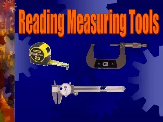
Reading Micrometer Caliper-parts • The first step in being able to read a micrometer is learning the names of the parts. • The face of the anvil and the face of the spindle are the contact surfaces. • The spindle and thimble turn together. • The ratchet/friction stop improves the repeatability of measurements for beginners. • A micrometer caliper is read at the point were the edge of the thimble crosses the barrel scale • Insure the lock is released before trying to turn the thimble..
Reading Micrometer Caliper-barrel • A micrometer caliper is read just like an ruler. • Start by determining the smallest whole unit, and then determine the values of each sub division. • The smallest whole unit is determined by the frame size. • One (1) inch frame = 0.0 smallest whole unit • Two (2) inch frame = 1.0 smallest whole unit. • Etc. • The micrometer barrel scale is one (1) inch long and is divided into ten (10) sections. • Each number on the barrel scale = 1/10 or 0.1 inch.
Reading Micrometer Caliper-barrel • Each 1/10 of an inch on the barrel scale is divided into 4 segments. • Each short line = 0.25 inches (25 thousands of an inch).
Reading Micrometer Caliper-thimble • The last step is reading the value on the thimble scale. • The thimble scale subdivides the last segment on the barrel scale. • The smallest segment on the barrel is 25 thousands (0.025). • The thimble is divided into 25 segments = 1/1,000 or 0.001 inch.
Micrometer Caliper Example • Determine the reading for the micrometer caliper in the illustration. • Smallest whole unit 0.000 • Tenths of an inch 0.300 • Twenty five thousands ( 0.025 x 2 ) 0.050 • Thousands 0.015 Sum (measurement) 0.365
Micrometer Caliper-digital • Most measuring tools are available with a digital readout. • Advantages • Easier to read. • Can be interfaced with data collection devices for automatic recording. • Easy to convert between English and metric units. • Disadvantages • Requires battery • More expensive
Inside Micrometer • Inside micrometers have been replaced by dial calipers and other tools for small gas engines. • The principles for reading are the same. • The primary difference is determining the smallest whole unit. • The physical size of the micrometer limits the smallest whole unit to 1 or 1-1/2 inch. • Extensions are added to set the minimum size to the desired range.
Inside Micrometer Example Read the inside micrometer in the illustration. Smallest whole unit 1.500 Tenths 0.200 Twenty Five Thousands 0.025 Thimble 0.014 Sum (reading) 1.734
Inside Micrometer Example 2 • Inside micrometers use extensions to change the range of measurements. • Adding an extension increases the minimum measurement. In this example a 1/2 inch extension has been added. Smallest whole unit 2.000 Tenths 0.200 Twenty five thousands 0.075 Thousands 0.001 Reading 2.276 Note: when the zero on the thimble is close to the reference line and a 25 thousands line is close to the edge of the thimble, it may be difficult to determine if the last line that should be counted. If the thimble zero is above the reference line the line is not counted. If it is below it should be counted.
Depth Gauge Micrometer • Depth gauge micrometers are used to measure the depth of blind holes, slots, key ways, etc. • The spindle length can be changed to set the micrometer for the desired range of measurement. • To read a depth gauge micrometer you must visualize the distance that has been covered by the thimble. Thimble Spindle
Depth Gauge Micrometer Example Read the depth gauge micrometer in the illustration Smallest whole unit 0.000 Tenths 0.800 Twenty Five Thousands 0.050 Thousands 0.017 Sum (reading) 0.867
Introduction • Calipers can be direct reading or measuring transferring tools. • Direct reading calipers are capable of a wider measurement range than micrometer calipers. • Six (6), eighteen (18) and twenty four (24) inch are popular. • Three common designs of direct reading calipers; • Vernier • Dial • Digital
Vernier Caliper • Vernier calipers are an old tool that has been mostly replaced by dial and digital calipers. • They are manufactured with decimal scales, metric scales and fractional scales. • The Vernier scale is still used on many mechanical measuring tools.
Vernier Scale • A Vernier is a mechanical means of magnifying the last segment on the main scale so addition subdivisions can be made. • The reference point is the 0 on the vernier scale. • To read a Vernier, the line of coincidence must be located. • The line of coincidence (LOC) is the line on the Vernier that coincides with a line on the main scale. • Illustration LOC = 19 • In theory only one LOC is possible, but usually when reading the vernier it appears several exist. When this occurs pick the middle line.
Vernier Caliper-practice Read the Vernier caliper in the illustration. • Smallest whole unit 1.000 • Tenths of an inch 0.200 • Twenty five thousands 0.000 • Vernier scale 0.011 Sum (measurement) 1.211 LOC
Dial Caliper A dial replaces the Vernier. This makes the caliper easier to read. The reader must still determine the units and graduations.
Introduction • Measurement transferring tools are tools that collect a measurement, but do not have a scale to read the measurement. • Common tools are: • Spring calipers • Dividers • Telescoping gauges • Ball gauges
Spring Calipers • Spring calipers are used to transfer measurements. • Three types of spring calipers • Outside • Inside • Hermaphrodite
Dividers • Dividers are very useful for laying out several equal distances or transferring a distance measurement when other measuring devices cannot be used.
Telescoping gages • Telescoping gages are used to measure inside diameters. • One or both ends are spring loaded so they can be retracted and inserted into the hole being measured. • The measurement is made with a caliper or micrometer.
Ball Gauges • Ball gauges are use to transfer measurements that are too small for telescoping gauges. • The ball is split and a tapered wedge is used to increase and decrease the diameter of the ball halves.