Download
1 / 42
420 likes | 641 Vues
Robust Non-Linear Observer for a Non-collocated Flexible System. Mohsin Waqar Intelligent Machine Dynamics Lab Georgia Institute of Technology December 12, 2007. Agenda. Project Motivation and Goals Non-collocated Flexible System and Non-minimum Phase Behavior Control Overview

E N D
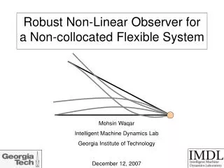
Robust Non-Linear Observer for a Non-collocated Flexible System Mohsin Waqar Intelligent Machine Dynamics Lab Georgia Institute of Technology December 12, 2007
Agenda • Project Motivation and Goals • Non-collocated Flexible System and Non-minimum Phase Behavior • Control Overview • Test-bed Overview • Plant Model • Optimal Observer – The Kalman Filter • Robust Observer – Sliding Mode • Project Roadmap • Project Roadmap
Motivation for Research – Flexible Robotic Arms 1) Manipulators with very large workspaces (long reach): Example - handling of nuclear waste. 2) Manipulators with constraint on mass: Example – space manipulators. 3) Manipulators with constraint on cost: Example – Camotion Depalletizer 4) Manipulators with Actuator/Sensor Non-collocation: Collocation can be impossible. Source: NASA.gov Source: camotion.com
Problem Statement • Contribute to the field of active vibration suppression in motion systems • Examine the usefulness of the Sliding Mode Observer as part of a closed-loop system in the presence of non-collocation and model uncertainty.
X What is a Flexible Robotic Arm? Source: Shabana, A. A. Vibration of Discrete and Continuous Systems. 1997. • Robotic arm is subject to torsion, axial compression, bending. • Structural stiffness, natural damping, natural frequencies and boundary conditions are important to consider. Note: pole = eigenvalue = mode = natural frequency
X What is a Flexible Robotic Arm? - References W.J. Book, “Modeling, Design, and Control of Flexible Manipulator Arms: A Tutorial Review,” Proceedings of the 29th Conference on Decision and Control, Dec. 1990. W.J. Book, “Structural Flexibility of Motion Systems in Space Environment,” IEEE Transactions on Robotics and Automation, Vol. 9, No. 5, pp. 524-530, Oct. 1993. W.J. Book, “Flexible Robot Arms,” Robotics and Automation Handbook., pp. 24.1-24.44, CRC Press, Boca Raton, FL, 2005.
Non-Minimum Phase Behavior (in continuous time system) • Causes: • Combination of non-collocation of actuators and sensors and the flexible nature of robot links • Detection: • System transfer function has positive zeros. • Effects: • Limited speed of response. • Initial undershoot (only if odd number of pos. zeros). • Multiple pos. zeros means multiple direction reversal in step response. • PID control based on tip position fails. Source: Cannon, R.H. and Schmitz, E. “Initial Experiments on the End-Point Control of a Flexible One-Link Robot.” 1984.
Non-Minimum Phase Behavior(in continuous time system) • Effects: • Limited gain margin (limited robustness of closed-loop system) • Model inaccuracy (parameter variation) becomes more troubling (Zero- flipping). Im X X X Re
Non-Minimum Phase Behavior - References R.H. Cannon and D. E. Rosenthal, “Experiments in Control of Flexible Structures with Noncolocated Sensors and Actuators,” J. Guidance, Vol. 7, No. 5, Sept.-Oct. 1984. R.H. Cannon and E. Schmitz, “Initial Experiments on the End-Point Control of a Flexible One-Link Robot,” International Journal of Robotics Research, 1984. D.L. Girvin, “Numerical Analysis of Right-Half Plane Zeros for a Single-Link Manipulator,” M.S. Thesis, Georgia Institute of Technology, Mar. 1992. J.B. Hoagg and D.S. Bernstein, “Nonminimum-Phase Zeros,” IEEE Control Systems Magazine, June 2007.
Control Overview Noise V + Commanded Tip Position u F y δ Feedforward Gain F Linear Motor Flexible Arm Sensors - Feedback Gain K Observer Design objective: Accuracy, repeatability and steadiness of the beam end point.
Test-Bed Overview R PCB 352a Accelerometer PCB Power Supply C LS7084 Quadrature Clock Converter Anorad Encoder Readhead Anorad Interface Module - + LV Real Time 8.2 Target PC w/ NI-6052E DAQ Board + NI SCB-68 Terminal Board 160VDC Anorad DC Servo Amplifier Linear Motor - PWM -10 to +10VDC
Test-Bed Rigid Sub-system ID Starting Parameters: Km=8.17; % overall motor gain [N/V] M=9.6; % base mass [kg] b=50; % track-base viscous damping [N*s/m] Using fmincon in Matlab with bounds: Km: +/- 25% M: +/- 10% b: (0,inf) Final Parameters with Step Input: [Km,M,b] = [6.9, 10.52, 38.97] With ramp input (0-5V over 2 sec): [Km,M,b] = [6.13, 10.56, 35.16]
Agenda • Project Motivation and Goals • Non-collocated Flexible System and Non-minimum Phase Behavior • Control Overview • Test-bed Overview • Plant Model • Optimal Observer – The Kalman Filter • Robust Observer – Sliding Mode • Project Roadmap • Project Roadmap
Flexible Arm Modeling Lumped Parameter System (or Discrete System) Distributed Parameter System (or Continuous System) • Finite degrees of freedom. • Described by one second-order ODE per degree/order of the system. Mashner (2002) Beargie (2002) • Symbolic form retains infinite degrees of freedom and non-minimum phase characteristics. • Describes rigid body motion of link and elastic deflection of link. • Described by second order PDE. Approaches: 1) Lagrangian: Obergfell (1999) 2) Newton Euler: Girvin (1992) Approximate methods: 3) Transfer Matrix Method: Krauss (2006), Girvin (1992) 4) Assumed Modes Method: Sangveraphunsiri (1984), Huggins (1988), Lane (1996)
Flexible Arm Modeling – Assumed Modes Method E, I, ρ, A, L m F w(x,t) x • Assumptions: • Uniform cross-section • 3 flexible modes + 1 rigid-body mode • Undergoes flexure only (no axial or torsional displacement) • Linear elastic material behavior • Horizontal Plane (zero g) • No static/dynamic friction at slider • Light damping (ζ << 1)
E, I, ρ, A, L m w(x,t) F x Flexible Arm Modeling – Assumed Modes Method Geometric Boundary Conditions: For i = 1 to 4 Ritz Basis Functions: Source: J.H. Ginsberg, “Mechanical and Structural Vibrations,” 2001
E, I, ρ, A, L m w(x,t) F x Flexible Arm Modeling – Assumed Modes Method
E, I, ρ, A, L m w(x,t) F x Flexible Arm Modeling – Assumed Modes Method
Flexible Arm Model vs Experimental AMM Model with Optimization Bounds: (0,inf) Length and Tip Mass +/- 25% All Others AMM Model with Optimization Bounds: +/- 25% On All Parameters Experimental Data
Flexible Arm Model vs Experimental • System ID setup: • Loop rate 1khz • Closed-loop PID • 0-40hz Chirp Reference Signal with 0.1-0.5 cm p-p amplitude • 15 data sets averaged
Agenda • Project Motivation and Goals • Non-collocated Flexible System and Non-minimum Phase Behavior • Control Overview • Test-bed Overview • Plant Model • Optimal Observer – The Kalman Filter • Robust Observer – Sliding Mode • Project Roadmap • Project Roadmap
Performance Criteria for Observer Study • What is a useful observer anyway? • Robust (works most of the time) • Accuracy not far off from optimal estimates • Not computationally intensive • Straightforward design • Uses simple rather than a complex plant model
A Hypothesis for Observer Study WHOOPS…PARABOLAS SHOULD BE FACING UPPPP!!!!!!! SMO Estimate Mean Square Error (MSE) Kalman Filter (KF) -50% -25% 0 25% 50% % Deviation in some Beam Parameter
Overview of Steady State Kalman Filter • Why Use? • Needed when internal states are not measurable directly (or costly). • Sensors do not provide perfect and complete data due to noise. • No system model is perfect • Notable Aspects: • Designed off-line (constant gain matrix) and reduced computational burden • Minimizes sum of squares of estimate error (optimal estimates) • Predictor-Corrector Nature • Shortcomings: • Limited robustness to model parameter variation • Steady State KF gives sub-optimal estimates at best
How it works - Kalman Filter Plant Dynamics Kalman Filter State Estimates with minimum square of error Measurement & State Relationships Noise Statistics Initial Conditions Filter Parameters: Noise Covariance Matrix Q – measure of uncertainty in plant. Directly tunable. Noise Covariance Matrix R – measure of uncertainty in measurements. Fixed. Error Covariance Matrix P– measure of uncertainty in state estimates. Depends on Q. Kalman Gain Matrix K – determines how much to weight model prediction and fresh measurement. Depends on P.
v u x y + r F B 1/s C + - A + L - + B 1/s C + ~A K How it works - Kalman Filter • Filter Design: • Find R and Q • 1a) For each measurement, find μ and σ2 to get R • 1b) Set Q small, non-zero • 2. Find P using Matlab CARE fcn • Find L=P*C'*inv(R) • Observer poles given by eig(~A-LC) • 5. Tune Q as needed
v u x y + r F B 1/s C + - A + L - + B 1/s C + ~A K How it works - Kalman Filter
Kalman Filter – LabVIEW Simulation Observer model = Plant model
Kalman Filter – LabVIEW Simulation Plant model: A + ΔA Δ A may be from system wear and tear or change in tip mass
Kalman Filter – Testbed On-Line Estimation Note: Accelerometer DC Bias of -0.67 volts or -6.61 m/s^2
Agenda • Project Motivation and Goals • Non-collocated Flexible System and Non-minimum Phase Behavior • Control Overview • Test-bed Overview • Plant Model • Optimal Observer – The Kalman Filter • Robust Observer – Sliding Mode • Project Roadmap • Project Roadmap
Sliding Mode Observer – Lit. Review • Slotine et al. (1987) – Suggests a general design procedure. Simulations shows superior robustness properties. • Chalhoub and Kfoury (2004) – 4th order observer with single measurement. Adapts Slotine’s design approach with modifications to observer structure. Presents a unique method for selecting switching gains. Simulations of a single flexible link with observer in closed-loop. Shows KF unstable in presence of uncontrolled modes while SMO remains stable. • Chalhoub and Kfoury (2006) – 6th order observer with 3 measurements. Same approach as earlier paper. Simulations of the rigid/flexible motion in IC engine.
Sliding Mode Observer – Lit. Review Kim and Inman (2001) – SMO design based on Lyapunov equation. Unstable estimates by KF in presence of uncontrolled modes while SMO remains stable. Simulations and experimental results of closed-loop active vibration suppression of cantilevered beam (not a motion system). Zaki et al. (2003) – 14th order observer with 3 measurements, with design based on Lyapunov equation. Experimental results (including parameter variation studies) from three flexible link testbed with PD control. Observer in open loop. Elbeheiry and Elmaraghy (2003) – 8th order observer with two measurements, with design based on Lyapunov equation. Simulations and experimental results from 2 link flexible joint testbed with PI control. Observer in open loop.
Sliding Mode Observer – Definitions • Sliding Surface – A line or hyperplane in state-space which is designed to accommodate a sliding motion. • Sliding Mode – The behavior of a dynamic system while confined to the sliding surface. • Signum function (Sgn(s)) if • Reaching phase – The initial phase of the closed loop behaviour of the state variables as they are being driven towards the surface.
Design a sliding surface. One surface per measurement. Design a sliding condition to reach the sliding surface in finite time. Design sliding observer gains to satisfy the sliding condition. Sliding Mode Observer – 3 Basic Design Steps
Sliding Mode Observer – Overview Example: Sliding Surface Single Sliding Surface Dynamics on Sliding Surface Sliding Condition Error Vector Trajectory (0,0)
Sliding Mode Observer Form Example: Observer Error Dynamics: Luenberger Observer: Is due to model imperfection. Has potential to destabilize observer error dynamics. Sliding Mode Observer:
Sliding Mode Observer Form General Form: Error Dynamics: + bounded nonlinear perturbations With proper selection of K which is based on some P, the Lyapunov function candidate can be used to show that is negative definite and so error dynamics are stable.
Sliding Mode Observer LabVIEW Simulation Simplified Flexible Arm Model: n=4, y=x1 (tip position) Plant zeros: -0.7+i1.3e7, -0.7-i1.3e7, 2.75 Simulation Parameters: Parameter Mismatch: 100% (spring constant) deltaF for SMO Design: 20% Eta for SMO Design: 0.05 No K No L L + K MSE: 0.0001 Just L MSE: 0.00076
Roadmap December 2007: Extend SMO to AMM Model and 2 measurements January 2008: SMO with Closed Loop Control Simulation KF with Closed Loop Control on Testbed SMO with Closed Loop Control on Testbed February 2008: Conduct Parameter Studies
Roadmap December 2007: Extend SMO to AMM Model and 2 measurements January 2008: SMO with Closed Loop Control Simulation KF with Closed Loop Control on Testbed SMO with Closed Loop Control on Testbed February 2008: Conduct Parameter Studies Questions?