Download
1 / 31
310 likes | 440 Vues
NEEP 541 – Material Properties. Fall 2003 Jake Blanchard. Outline. Materials in Reactors Fission Fusion Material Properties Tensile tests Impact tests Creep tests. Materials in Reactors. Fission Fuel Cladding Moderator Core structure Reflector Control rods Coolant

E N D
NEEP 541 – Material Properties Fall 2003 Jake Blanchard
Outline • Materials in Reactors • Fission • Fusion • Material Properties • Tensile tests • Impact tests • Creep tests
Materials in Reactors • Fission • Fuel • Cladding • Moderator • Core structure • Reflector • Control rods • Coolant • Pressure vessel • shielding • Fusion • Fuel • Structure • Tritium breeder • Coolant • insulators • shielding
Fission • Primary radiation damage is in fuel and cladding • Cladding: • Adequate strength (T, fluence) • Corrosion resistance • Thermal conductivity • Neutronics (low absorption) • Available resources • Fabricability • Inexpensive
Cladding Materials • Low thermal absorption cross section • Al • Mg • Zr • Be • High thermal absorption cross section • Nb • Mo • Ta • V • Ti • Steel
Fusion Structure Requirements • Same as fission plus… • Low swelling • Low embrittlement • Typical Materials • Austenitic steel (316 SS) • Ferritic steel (lately ODS FS) • Refractory alloys • composites
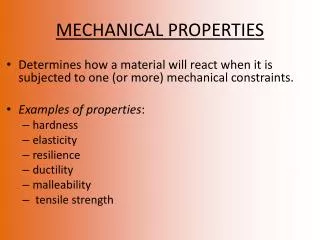
Radiation Effects • Radiation hardening (increase in strength) • Embrittlement (decrease in ductility) • Swelling (volume increase due to voids) • Irradiation creep
Tests • Tensile tests (modulus, ductility, strength) • Tube burst tests (creep) • Impact tests (ductility, fracture toughness)
Understanding the Tensile Test • A0=cross sectional area before test (in test section) • A=cross sectional area during test (load=P) • L0=section length before test • L=section length during test
Tensile Tests • Engineering stress=eng=P/A0 • True Stress=true=P/A • Before necking, A~A0 • Engineering strain==(L-L0)/L0 • True strain=
When does necking start? • Plastic Instability (dP=0) Volume is conserved
Plastic Instability Necking occurs when slope of true stress-true strain curve=true stress
Plastic Instability • suppose
Impact Testing • Test for ductility • Measure energy absorbed during fracture
Typical Results • DBTT=ductile to brittle transition temperature Upper shelf Lower shelf E (J) irradiated 40 T DBTT
Creep Tests • Apply load and measure deformation as a function of time primary secondary tertiary Creep strain time
Burst Test Analysis Slice cylinder vertically p
Burst Test Analysis Slice cylinder horizontally (picture is shown cut away vertically as well)
Burst Test Analysis • Uniaxial (1-D tensile test) • Constant stress
Burst Test Analysis • Negative radial strain means that wall gets thinner • Zero axial strain means length doesn’t change • Positive hoop strain means radius increases • Analysis assumes small strain, constant stress • For large strain, wall thins and stress increases, leading to rupture