Download
1 / 36
400 likes | 1.29k Vues
2. Usefulness of PID Controls. Most useful when a mathematical model of the plant is not availableMany different PID tuning rules availableOur sourcesK. Ogata, Modern Control Engineering, Fourth Edition, Prentice Hall, 2002, Chapter 10IEEE Control Systems Magazine, Feb. 2006, Special issue on PID control .

E N D
1. 1 Proportional-Integral-Derivative (PID) Controllers Stanislaw H. Zak
School of Electrical and Computer Engineering
ECE 382
Spring 2008
2. 2 Usefulness of PID Controls Most useful when a mathematical model of the plant is not available
Many different PID tuning rules available
Our sources
K. Ogata, Modern Control Engineering, Fourth Edition, Prentice Hall, 2002, Chapter 10
IEEE Control Systems Magazine, Feb. 2006, Special issue on PID control
3. 3 Type A PID Control Transfer function of PID controller
The three term control signal
4. 4 PID-Controlled System PID controller in forward path
5. 5 PID Tuning Controller tuning---the process of selecting the controller parameters to meet given performance specifications
PID tuning rules---selecting controller parameter values based on experimental step responses of the controlled plant
The first PID tuning rules proposed by Ziegler and Nichols in 1942
Our exposition based on K. Ogata, Modern Control Engineering, Prentice Hall, Fourth Edition, 2002, Chapter 10
6. 6 PID Tuning---First Method Start with obtaining the step response
7. 7 The S-shaped Step Response Parameters of the S-shaped step response
8. 8 The S-Shaped Step Response The S-shaped curve may be characterized by two parameters: delay time L and time constant T
The transfer function of such a plant may be approximated by a first-order system with a transport delay
9. 9 PID Tuning---First Method
10. 10 Transfer Function of PID Controller Tuned Using the First Method
11. 11 Ziegler-Nichols PID Tuning---Second Method Use the proportional controller to force sustained oscillations
12. 12 PID Tuning---Second Method Measure the period of sustained oscillation
13. 13 PID Tuning
14. 14 Transfer Function of PID Controller Tuned Using the Second Method
15. 15 Example 1---PID Controller for DC Motor Plant---Armature-controlled DC motor; MOTOMATIC system produced by Electro-Craft Corporation
Design a Type A PID controller and simulate the behavior of the closed-loop system; plot the closed-loop system step response
Fine tune the controller parameters so that the max overshoot is 25% or less
16. 16 Modeling the Armature Controlled DC Motor
17. 17 Transfer Function of the DC Motor System Transfer function of the DC motor
where C(s) is the angular displacement of the motor shaft and U(s) is the armature voltage
18. 18 Tuning the Controller Using the Second Method of Ziegler and Nichols Use the Routh-Hurwitz stability test;
see p. 173 of the Text
Determine
Determine
Compute the controller parameters
19. 19 Generating the Step Response t=0:0.00005:.017;
K_cr=12.28; P_cr=135;
K=0.075*K_cr*P_cr; a=4/P_cr;
num1=K*[1 2*a a^2]; den1=[0 1 0];
tf1=tf(num1,den1);
num2=[0 0 0 0.1464];
den2=[7.89e-007 8.25e-004 0.00172 0];
tf2=tf(num2,den2);
tf3=tf1*tf2;
sys=feedback(tf3,1);
y=step(sys,t); m=max(y);
20. 20 Closed-loop System Performance
21. 21 Example 2 (Based on Ex. 10-3 in Ogata, 2002) Use a computational approach to generate an optimal set of the DC motor PID controller�s parameters
Generate the step response of the closed-loop system
22. 22 Optimizing PID Parameters t=0:0.0002:0.02;
for K=5:-0.2:2%Outer loop to vary the values of %the gain K
for a=1:-0.01:0.01;%Outer loop to vary the %values of the parameter a
num1=K*[1 2*a a^2]; den1=[0 1 0];
tf1=tf(num1,den1);
num2=[0 0 0 0.1464];
den2=[7.89e-007 8.25e-004 0.00172 0];
tf2=tf(num2,den2);
tf3=tf1*tf2;
sys=feedback(tf3,1);
y=step(sys,t); m=max(y);
23. 23 Finishing the Optimizing Program if m<1.1 & m>1.05;
plot(t,y);grid;set(gca,'Fontsize',font)
sol=[K;a;m]
break % Breaks the inner loop
end
end
if m<1.1 & m>1.05;
break; %Breaks the outer loop
end
end
24. 24 Closed-Loop System Performance
25. 25 Modified PID Control Schemes If the reference input is a step, then because of the presence of the derivative term, the controller output will involve an impulse function
The derivative term also amplifies higher frequency sensor noise
Replace the pure derivative term with a derivative filter---PIDF controller
Set-Point Kick---for step reference the PIDF output will involve a sharp pulse function rather than an impulse function
26. 26 The Derivative Term Derivative action is useful for providing a phase lead, to offset phase lag caused by integration term
Differentiation increases the high-frequency gain
Pure differentiator is not proper or causal
80% of PID controllers in use have the derivative part switched off
Proper use of the derivative action can increase stability and help maximize the integral gain for better performance
27. 27 Remedies for Derivative Action---PIDF Controller Pure differentiator approximation
where is a small parameter, around, 0.1
Pure differentiator cascaded with a first-order low-pass filter
28. 28 The Set-Point Kick Phenomenon If the reference input is a step function, the derivative term will produce an impulse (delta) function in the controller action
Possible remedy---operate the derivative action only in the feedback path; thus differentiation occurs only on the feedback signal and not on the reference signal
29. 29 Eliminating the Set-Point Kick PID controller revisited
30. 30 Eliminating the Set-Point Kick---Finding the source of trouble More detailed view of the PID controller
31. 31 Eliminating the Set-Point Kick---PI-D Control or Type B PID Operate derivative action only in the feedback
32. 32 I-PD---Moving Proportional and Derivative Action to the Feedback I-PD control or Type C PID
33. 33 I-PD Equivalent to PID With Input Filter (No Noise) Closed-loop transfer function C(s)/R(s) of the I-PD-controlled system
34. 34 PID-Controlled System Closed-loop transfer function C(s)/R(s) of the PID-controlled system with input filter
After manipulations it is the same as the transfer function of the I-PD-controlled closed-loop system
35. 35 PID, PI-D and I-PD Closed-Loop Transfer Function---No Ref or Noise In the absence of the reference input and noise signals, the closed-loop transfer function between the disturbance input and the system output is the same for the three types of PID control
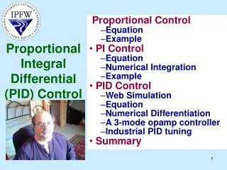
36. 36 The Three Terms of Proportional-Integral-Derivative (PID) Control Proportional term responds immediately to the current tracking error; it cannot achieve the desired setpoint accuracy without an unacceptably large gain. Needs the other terms
Derivative action reduces transient errors
Integral term yields zero steady-state error in tracking a constant setpoint. It also rejects constant disturbances
37. 37 Summary PID control---most widely used control strategy today
Over 90% of control loops employ PID control, often the derivative gain set to zero (PI control)
The three terms are intuitive---a non-specialist can grasp the essentials of the PID controller�s action. It does not require the operator to be familiar with advanced math to use PID controllers
Engineers prefer PID controls over untested solutions