Download
1 / 26
260 likes | 380 Vues
BRABENDER PRESENTATION. FEEDER DESIGN FOR ENERGETIC APPLICATIONS INVOLVING CONTINUOUS MIXERS AND EXTRUDERS PRESENTED October 31, 2002 By: Andy Kovats Brabender Technologie Inc. 1.0 Introduction 2.0 Feed Device Selection: Feed Device Selection Criteria

E N D
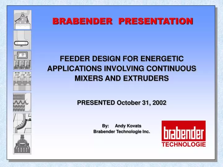
BRABENDER PRESENTATION FEEDER DESIGN FOR ENERGETIC APPLICATIONS INVOLVING CONTINUOUS MIXERS AND EXTRUDERS PRESENTED October 31, 2002 By: Andy Kovats Brabender Technologie Inc.
1.0 Introduction 2.0 Feed Device Selection: Feed Device Selection Criteria - Single screw, twin screw, vibratory tray Modifications for XP Requirements 3.0 Continuous Loss-in-Weight Feeders: LIW Feeder Scales – besides weighing performance, what are some noted features Sizing the Refill Rate for a LIW Feeder Venting Alternatives and Flexible Connection of LIW Feeders Loss-in-Weight Feeder Modifications for XP Requirements 4.0 Continuous Loss-in-Weight (LIW) Feeder Performance Considerations when Designed to meet XP Requirements 5.0 Summary Presentation Agenda
1.0 Introduction • Energetics feeders feed explosive ingredients in • explosive atmospheres. • Special design considerations include: • screw or feed device non-sparking; low shear; • scale design to counteract heavy dead load – e.g.: explosion proof motors; • explosion proofing components; • feed rate accuracy expectations.
SCREW DIA. SCREW PITCH SCREW RPM VOLUMETRIC FEED RATE CU. FT./HR. Single Screw 18mm 13mm 220 1.1 Twin Screw 20mm 12mm 425 0.9 Tray Width(V) Vibratory Tray 30mm 3.2 2.0 Feed Device Selection Feed Device Selection Criteria E.g.: Ammonium Per chlorate Bulk Density – 80 lbs./cu. ft. Feed – 40 lbs./hr. Volumetric Feed Rate – 40/80 = 0.5 cu.ft./hr. Using this as an example, we will compare the relative sizes of 3 common feed devices.
TYPE DESCRIPTION FEED CHARACTERISTICS Single Spiral Screw open flights (pigtail), have a small surface area for ingredient adherence with center rod stiffening stainless steel material of construction low build-up on screws, low shear on ingredient for higher bulk densities and where an outboard bearing is required (to avoid screw/tube (metal-to-metal) contact) Single Blade Screw closed flights with extended shaft more surface area for build up on screw, higher shear on ingredient for outboard bearing Twin Concave Screw intermeshing, self-wiping screws, low volume per flight relative to screw diameter large inlet to screws compared to single screw – same rate since flight volume is low, screws can operate at higher rpm and achieve a high fill efficiency, larger inlet reduces chance of bridging, self-wiping maintains geometry integrity Common Screw Types Vibrating Tray - for heavy powders (above 40 lbs./cu. ft.) and granules; - especially good for abrasive ingredients; - since there are no rotating shafts/metal-to-metal contact, device is simple; - requires amplitude feedback/resonant frequency control to achieve accuracy.
Modifications for XP Requirements • All screws with outboard bearings; • All seals/bearings purged inboard, outboard, agitators; • Internal surfaces 2B finish with welds ground smooth; • Some processes need No. 4 polish (180 grit); • All welds dye penetration checked; • Grounding straps across gaskets; • External grounding lug on feeder; • Vibration tray feeders are typically not manufactured with the electromagnetic drive meeting Hazardous Environment Codes. As a result, care must be taken to ensure that this is achieved.
Description of Scale Number of Load Cells Feeder Connection to Scale Flexure Frame Scale 1 Feeder base sits on weighed support Platform Scale 1 – normally Feeder base sits on top plate of scale Three load cell suspension 3 Feeder hopper supported (feeder may be suspended from the hopper) Two load cell suspension 2 Feeder base supported at hopper elevation 3.0 Continuous Loss-in-Weight Feeders LIW Feeder Scale – Besides Weighing Performance, what are some noted features?
Check List for LIW Feeder Scale Evaluation Type of Load Cell - digital/analog Number of Load Cells - one, two, three Load Cell Response - fast/slow – a function of load cell movement from full load to no load Load Cell Filter - included/not included, one load/ several loads, selection easy/difficult Scale Lock Down - included/not included, easy/tedious Junction Boxes for Motor/ Load Cell - supplied/not supplied, wired/not wired External Process Connection - included/not included, mounted/not mounted, with/without flex Feeder Mounted Wired - Tested Locked at Factory - yes/no
Sizing the Refill Rate for a LIW Feeder Using 10 seconds as a desired refill time, the following calculations are made: Max. Feed Rate - 240 lbs./hr. (min. rate 60 lbs./hr.) Bulk Density - 40 lbs./cu. ft. Number of Refills/Hr. - 15 at max. feed rate Weigh Hopper Refill Volume - 60% (20% heel before refilling and 20% free board) Calculation Weigh Hopper Volume = Max. Feed Rate bulk density refills/hr. refill volume % = 240 40 15 6 = 0.67 cu. ft. Refill Volume = Weigh Hopper Volume X refill Volume % = 0.67 X 0.6 = 0.4 cu. ft. Refill Time = 10 seconds Refill Rate = 0.4 cu. ft. in 10 seconds = 144 cu. ft./hr. (5,760 lbs./hr.) Rule of Thumb – Multiply the max. feed rate X 24 to determine the refill rate to achieve refill in 10 seconds (assumes weigh hopper volume calculated as per example above).
Venting Alternatives and Flexible Connection for LIW Feeders
CL DIV GR MOTORS AC MOTORS DC ENCLOSURES & JUNCTION BOXES LOAD CELL WIRING & CONDUIT DIGITAL ANALOG FLEXIBILITY NOT REQUIRED FLEXIBILITY REQUIRED I 1 A B TEFC/TENV WITH TYPE “X” PURGE TEFC/TENV WITH TYPE “X” PURGE DIGITAL PICKUP CONNECTED THRU INTRINSICALLY SAFE BARRIERS PURGED ENCLOSURE (USE TYPE “X” PURGING) INTRINSICALLY SAFE LOADCELL OR CONNECTED THRU INTRINSICALLY SAFE BARRIERS RATED CLI DIV 1 OR CONNECTED THRU INTRINSICALLY SAFE BARRIERS THREADED RIGID CONDUIT WITH APPROVED FITTINGS AND SEALS FLEXIBLE CONDUIT APPROVED FOR CLI DIV 1 AND APPROVED FITTINGS & SEALS C RATED CLI GRC NEMA 7 D RATED CLI GRD RATED CLI GRD NEMA 7 SPEED I 2 A B TEFC OR TENV TEFC/TENV WITH TYPE “X” PURGING DIGITAL PICKUP CONNECTED THRU INTRINSICALLY SAFE BARRIERS PURGED ENCLOSURE (USE TYPE “X” PURGING) INTRINSICALLY SAFE LOADCELL OR CONNECTED THRU INTRINSICALLY SAFE BARRIERS RATED CLI DIV 2 OR CONNECTED THRU INTRINSICALLY SAFE BARRIERS THREADED RIGID CONDUIT WITH APPROVED FITTINGS AND SEALS HARD USAGE SO CABLE WITH APPROVED SEALS SENSOR C NEMA 7 D RATED CLI GRD NEMA 7 II 1 E TEFC OR TENV WITH TYPE “X” PURGING TEFC OR TENV WITH TYPE “X” PURGING DIGITAL PICKUP CONNECTED THRU INTRINSICALLY SAFE BARRIERS NEMA 9 INTRINSICALLY SAFE LOADCELL OR CONNECTED THRU INTRINSICALLY SAFE BARRIERS RATED CLII DIV 1 OR CONNECTED THRU INTRINSICALLY SAFE BARRIERS THREADED RIGID CONDUIT WITH APPROVED FITTINGS AND SEALS HARD USAGE SO CABLE WITH BUSHED DUST TIGHT FITTINGS F RATED CLII GRG RATED CLII GRF NEMA 9 G RATED CLII GRG RATED CLII GRG NEMA 9 II 2 E F G TEFC OR TENV TEFC OR TENV ANALOG TACH GENERATOR TENV ENCLOSURE DUST TIGHT NEMA 9 OR NEMA 12 DUST TIGHT ENCLOSURE DUST TIGHT ENCLOSURE HARD USAGE SO CABLE WITH BUSHED DUST TIGHT FITTINGS HARD USAGE SO CABLE WITH BUSHED DUST TIGHT FITTINGS LIW Feeder Modifications for XP Requirements
4.0 Continuous Loss-in-Weight (LIW) Feeder Performance Considerations When Designed to Meet XP Requirements • Dimensional Size Increase. • Increased Dead Load. • External Connections.
5.0 Summary The following is a list of comments relating to information and conclusions presented in this discussion: • Feed rate accuracy is jeopardized when the various components are modified to meet XP requirements. The results achieved in a lab test need to be considered with regard for the equipment modifications necessary to meet the Hazardous Environment Classification. • The acceptable method of equipment design to meet an XP requirement is determined by the end user. The technique to supply equipment capable of meeting the XP Classification should be reviewed with the equipment supplier carefully since there is more than one method of meeting the XP requirement. • For Loss-in-Weight feeders, select scale mounted electrical components that have a low weight for XP requirements. • Feeders for low feed rates need careful design to ensure feed rate repeatability accuracy is not compromised.
Brabender Technologie Inc. 6500 Kestrel Rd. Mississauga, Ontario L5T 1Z6 Office - 905-670-2933 Fax - 905-670-2557 toll-free - 888-284-4574 Presented By: Andy Kovats akovats@brabenderti.com www.brabenderti.com