Download
1 / 25
250 likes | 254 Vues
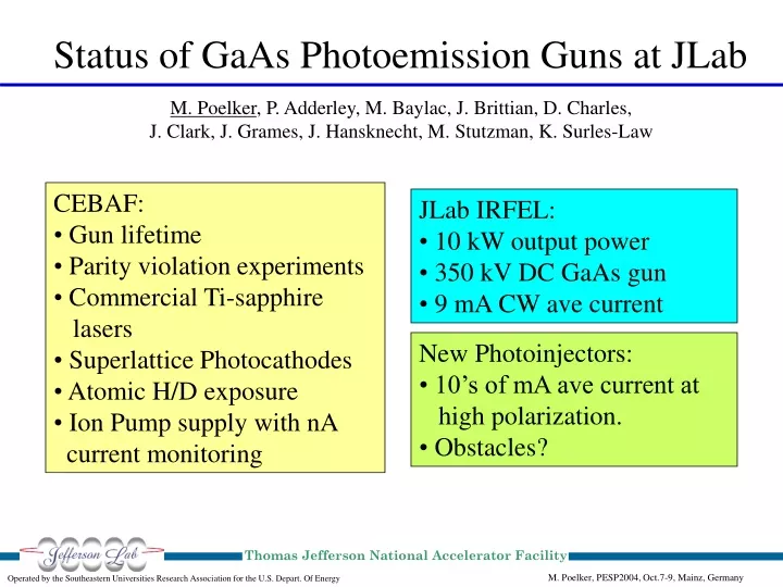
Thomas Jefferson National Accelerator Facility. M. Poelker, PESP2004, Oct.7-9, Mainz, Germany. Operated by the Southeastern Universities Research Association for the U.S. Depart. Of Energy. Status of GaAs Photoemission Guns at JLab.

E N D
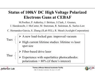
Thomas Jefferson National Accelerator Facility M. Poelker, PESP2004, Oct.7-9, Mainz, Germany Operated by the Southeastern Universities Research Association for the U.S. Depart. Of Energy Status of GaAs Photoemission Guns at JLab M. Poelker, P. Adderley, M. Baylac, J. Brittian, D. Charles, J. Clark, J. Grames, J. Hansknecht, M. Stutzman, K. Surles-Law • CEBAF: • Gun lifetime • Parity violation experiments • Commercial Ti-sapphire • lasers • Superlattice Photocathodes • Atomic H/D exposure • Ion Pump supply with nA • current monitoring • JLab IRFEL: • 10 kW output power • 350 kV DC GaAs gun • 9 mA CW ave current • New Photoinjectors: • 10’s of mA ave current at • high polarization. • Obstacles?
CEBAF 2-Gun Photoinjector New cleanroom for lasers
Gun Charge Lifetime Measured over 2001 -2004 M. Baylac Gun Charge Lifetime Steadily Decreasing NEG pump replacement Summer 2003 improves lifetime 10 NEG pumps surround cathode/anode gap
complete partially complete approved Parity Violation Experiments at CEBAF
G0 Forward Angle was a Difficult Experiment • Very long experiment! • “commissioning” run: August 2002 – January 2003 • “engineering” run: October 2003 – February 2004 • “production” run: March 2004 – May 2004 • 31 MHz time structure caused problems; • Homemade lasers could not generate 70 ps pulses • Homemade lasers were not long-term stable • High bunch charge caused beam handling problems • Managing helicity correlated position asymmetry was painful, at least initially.
Injector acceptance 111 ps 70 uA 40 uA 20 uA 8 uA 2 uA 1 uA Current from gun Current delivered to Hall Aperture loss 8 times Higher Bunchcharge; ~ 2 pC/pulse Significant bunchlength growth Beam profile distortion when laser spot tightly focused at photocathode Lots of beamloss at apertures
G0 Exp used active feedback to control asymmetries Helicity correlated differences integrated over a few hours. • Pockel cell aligned using spinning linear polarizer • Rotating halfwaveplate sets asymmetries close to zero before turning feedback ON. • IA cell (waveplate+pockel cell+linear polarizer) used to correct charge asymmetry. • PZT mirror used to correct position asymmetries. • Helicity correlated charge and position asymmetry seen to converge to zero over the course of a few hours. Correlations: - Position differences induce charge asymmetry through scraping. - Charge asymmetry induces energy and position differences through rf cavity loading. - Position differences “appear” as energy differences at the dispersive point.
Helicity Correlated Beam Specs for g0 Forward Total of 744 hours (103 Coulombs)of parity quality beam with a 4 cut on parity quality. All parity quality specs have been achieved!!
Commercial Laser was critical to success of experiment. • Cavity length ~ 5 m • Tunable over ~ 20 nm at 780 nm and 850 nm. • Etalons provide range of pulsewidths from 10 p to 70 ps. • More than 250 mW power
499 MHz modelocked Ti-sapphire lasers for high current polarized beam experiments (~ 100 uA ave.) • 300 to 500 mW output power • 770 nm or 850 nm operation • Stable phase-locked pulse train • Maintenance required
HAPPEx Approach • In the Laboratory; • Compare pockels cells from different vendors • Choose cell with smallest birefringence gradient • In the Tunnel; • Without cell, verify good optics and laser polarization. • Align insertable halfwaveplate for 90 degree rotation. • Align pockel cell • Minimize optical beam steering by positioning laser on geometric center of cell. • With Beam; • Verify laser table measurements; plot e-beam HC position and intensity asymmetry vs rotating halfwave plate orientation for “ideal” cell voltages. Asymmetries should be small. • Adjust rotating waveplate orientation and cell voltages to minimize beam asymmetries. Use IA cell to apply charge asymmetry feedback. Minimize asymmetries at outset via careful choice and alignment of pockel cell. No position feedback.
Final beam quality numbers pending but preliminary results indicate HC specifications were met; From HAPPEx-H Gun3 superlattice GaAs Gun2 strained layer GaAs 14 mm • Gun3 lifetime was poor • Frequent laser spot moves were necessary • QE holes caused HC asymmetry variations
Superlattice Photocathode from SVT here here Preliminary here Wavelength (nm) Wavelength (nm) Wavelength (nm) QE (%) Polarization Analyzing Power photon electron From Hall A Compton Polarimeter • The highest polarization yet measured at CEBAF; ~ 85% • QE 0.8% versus 0.15% • Analyzing power 4 % versus 12%
SVT SuperlatticeSummary QE not constant • Highest polarization ever measured at JLab: P = 85% • Measurements of many samples at test stand indicates this is no fluke. • 5 times higher QEthan strained layer GaAs material (not yet demonstrated at tunnel). • Smaller analyzing powershould provide smaller inherent charge and position asymmetry. (Recent HAPPEx results do not support this claim.) • We suffered surface charge limit.QE drops with increasing laser power. A concern for high current experiments like Qweak.
QE vs hydrogen cleaning Typical H-dose to clean anodized samples QE (%) Drawback: Superlattice material is delicate Can’t clean with atomic hydrogen Makes it tough to anodize edge of photocathode Hydrogen exposure time (min) From M. Baylac et al., in press
Ion Pump Power Supplies with nanoA Current Monitoring Designed and constructed by J. Hansknecht Ion Pump Locations Pumps detect bad orbit and beamloss “Free” pressure monitoring at 10^-11 Torr Gun chamber pump Wien filter Y-chamber Laser chamber
10 kW for 1 sec. (2.5 kW ave power at ¼ DF) Ave. Power (kW) Courtesy C. H. Garcia and JLab FEL team
The JLAB FEL Injector is driven by a 350 kV DC GaAs Photocathode Gun Drive Laser Photocathode Ball cathode • PHOTOCATHODE PERFORMANCE • Photocathode QE~6% after initial activation at 532 nm • Photocathode delivers ~200 C between re-cesiations • Typical day of operations draws ~35 Coulombs • About 96% of previous QE is recovered with each re-cesiation • 12 activated cathodes and close to 40 re-cesiations performed on a single GaAs wafer in one year 40 cm Thomas Jefferson National Accelerator Facility FEL Operated by the Southeastern Universities Research Association for the U.S. Depart. Of Energy Courtesy C. H. Garcia and JLab FEL team
Demonstrated DC Photocathode Gunperformance at JLab IR-FEL Thomas Jefferson National Accelerator Facility FEL Operated by the Southeastern Universities Research Association for the U.S. Depart. Of Energy • Macropulse operation at 8 mA, 16 ms-long pulses at 2 Hz repetition rate. RF microstructure within macropulse. • CW operation at 9.1 mA with 75 MHz microstructure and 122 pC/bunch. • Gun routinely delivers 5 mA in pulsed and CW modes with 135 pC/microbunch. • Vacuum environment: 4.0E-11 Torr, 99.9% H2 Courtesy C. H. Garcia and JLab FEL team
JLab FEL program with unpolarized beam ELIC with circulator ring Ave. Beam Current (mA) First low polarization, then high polarization at CEBAF Year Source requirements for ELIC less demanding with circulator ring. Big difference compared to past talks. Few mA’s versus >> 100 mA of highly polarized beam. First polarized beam from GaAs photogun M. Poelker, EIC Workshop, March 15-17, 2004 Operated by the Southeastern Universities Research Association for the U.S. Dept. of Energy Thomas Jefferson National Accelerator Facility Continuing Trend Towards Higher Average Beam Current
Ion Linac and pre - booster IR IR Snake Solenoid 3 - 7 GeV electrons 30 - 150 GeV light ions CEBAF with Energy Recovery Beam Dump ELIC Layout One accelerating & one decelerating pass through CEBAF (A=1-40) Ion Linac and pre Ion Linac and pre Electron Cooling - - booster booster Electron circulator ring IR IR IR IR Snake Snake Solenoid Solenoid 3 3 - - 7 GeV 7 GeV electrons electrons 30 30 - - 150 GeV (light) ions 150 GeV light ions Electron Injector CEBAF with Energy Recovery CEBAF with Energy Recovery Beam Dump Beam Dump Thomas Jefferson National Accelerator Facility Operated by the Southeastern Universities Research Association for the U.S. Department Of Energy
C /c ~100 C /c 1/f c I CR CR Injector C = 1.5 km t I CR Circulator Ring t M. Poelker, EIC Workshop, March 15-17, 2004 ELIC e-Beam Specifications • Typical parameters; • Ave injector gun current 2.5 mA (and then 25 mA) • Micropulse bunch charge 1.6 nC • Micropulse rep rate 150 MHz (and then 1.5 GHz) • Macropulse rep rate ~ 2 kHz, 5 usec duration. Operated by the Southeastern Universities Research Association for the U.S. Dept. of Energy Thomas Jefferson National Accelerator Facility
Gun Issues for ELIC • Need 80% polarized e-beam. • Use SVT superlattice photocathode. 1% QE at 780 nm; • 6.3 mA/W/%QE • ~ 1 W provides 1/e operation at 2.5 mA • Commercial Ti-Sapp lasers with CW rep rates to 500 MHz provide 0.5 W. Homemade lasers provide ~ 2W. • Injector micropulse/macropulse time structure demands laser R&D. • 25 mA operation requires more laser power and/or QE. • Charge Limit? Yes, at 1.6 nC/bunch and low QE wafers. • Lifetime? Probably wise to improve vacuum (more later) • Gun HV ~ 500 kV to mitigate emittance growth. • Must limit field emission. M. Poelker, EIC Workshop, March 15-17, 2004 Operated by the Southeastern Universities Research Association for the U.S. Dept. of Energy Thomas Jefferson National Accelerator Facility
Gun Lifetime • CEBAF enjoys good gun lifetime; • ~ 200 C charge lifetime (until QE reaches 1/e of initial value) • ~ 100,000 C/cm2 charge density lifetime (we operate with a ~ 0.5 mm dia. laser spot) • Gun lifetime dominated by ion backbombardment. • So it’s reasonable to assume lifetime proportional to current density. • Use a large laser spot to drive ELIC gun. This keeps charge density small. Expect to enjoy the same charge density lifetime, despite higher ave. current operation, with existing vacuum technology. M. Poelker, EIC Workshop, March 15-17, 2004 Operated by the Southeastern Universities Research Association for the U.S. Dept. of Energy Thomas Jefferson National Accelerator Facility
Gun Lifetime cont. Lifetime Estimate; • Use 1 cm diameter laser spot at photocathode. • At 2.5 mA gun current, we deliver 9 C/hour, 216 C/week. • Charge delivered until QE falls to 1/e of initial value; • Need to test the scalability of charge lifetime with laser spot diameter. Measure charge lifetime versus laser spot diameter in lab. (J. Grames presentation this workshop) 100,000 C/cm2 *1 Wk/216 C * 3.14(0.5 cm)^2 = 360 Wks! 36 Weeks lifetime at 25 mA. M. Poelker, EIC Workshop, March 15-17, 2004 Operated by the Southeastern Universities Research Association for the U.S. Dept. of Energy Thomas Jefferson National Accelerator Facility