Download
1 / 31
310 likes | 316 Vues
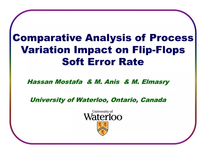
Comparative Analysis of Process Variation Impact on Flip-Flops Soft Error Rate. Hassan Mostafa & M. Anis & M. Elmasry University of Waterloo, Ontario, Canada. Outline. Introduction and Background Motivation and Objectives Simulation Procedure Results and Discussions Conclusions.

E N D
Comparative Analysis of Process Variation Impact on Flip-Flops Soft Error Rate Hassan Mostafa & M. Anis & M. Elmasry University of Waterloo, Ontario, Canada
Outline • Introduction and Background • Motivation and Objectives • Simulation Procedure • Results and Discussions • Conclusions Introduction and Background
Outline • Introduction and Background • Variability • Classification and Design methodologies • Sources • Variability and Yield • Soft Errors • Motivation and Objectives • Simulation Procedure • Results and Discussions • Conclusions Introduction and Background
Variability Classification • Die-to-Die (D2D) • Affects all devices on the chip in the same way • e.g., all devices on a chip have the same Vt • Within-Die (WID) • Variations within a single chip • Affecting devices on the same chip differently • e.g., devices on the same chip have different Vt D2D WID Die index Introduction and Background
Performance Distribution Design Methodology Cost (e.g. power) FAIL Nominal 50% Timing Yield FAIL Corner-Based 100% Timing Yield FAIL Statistical >99.9% Timing Yield Design Methodologies www.nowpublishers.com Introduction and Background
Process Variations Sources [1] • Random Dopant Fluctuations (RDF) • As CMOS devices are scaled, number of dopant atoms decreases • The number of dopant atoms has variations around its nominal value resulting in Vtvariations • σVtα (WL)-0.5 • As transistor area decreases with scaling, σVt increases • Channel Length Variation • Difficulty to control the critical dimensions at sub-wavelength lithography • Large variations in the channel length (L) • Vt α exp(-L)due to short channel effects • A small variations in L results in large variations in Vt T. C. Chen et al., ISSCC06 S. Borkar et al., DAC04 Variations increase with technology scaling Introduction and Background
Delay distribution PASS FAIL Delay Target delay Variability and Yield • Process variations causes the device parameters to have fluctuations around their nominal values • The system parameters such as delay and power have a spread around their nominal values • This result in a percentage of the systems does not meet the required function or the required parameter constraint • Yield loss Variability results in Yield loss Introduction and Background
Outline • Introduction and Background • Variability • Soft Errors • Sources and Mechanism • SER and Technology scaling • Impact of Variability on Soft Errors • Motivation and Objectives • Simulation Procedure • Results and Discussions • Conclusions Introduction and Background
Soft Errors: Sources and Mechanism • Soft errors cause a change of states in memory elements or transients in combinational circuits due to energetic radiation particles • Soft errors induced the highest failure rate of all other reliability mechanisms combined as technology scales due to lower capacitances and supply voltages [1] • Sources: • Alpha Particles • Emitted from packaging materials • Neutrons • Resulting from cosmic rays • Mechanism: • The particle penetrates the Silicon substrate inducing electron-hole pairs • These electron-hole pairs are collected by different mechanisms inducing a current pulse at the struck node • This current pulse may cause the node state to be flipped from 1-to-0 or from 0-to-1 www.wikipedia.com R. Baumann, TDMR05 [1] Texas Instraument, 2005; Introduction and Background
Soft Errors and Technology Scaling • Critical Charge (Qcritical) • The minimum amount of charge deposited at the struck node to produce a soft error • Soft Error Rate (SER) • SER α exp (- Qcritical) • With technology scaling • The bit SER is flat • The system SER is increasing due to the increased density of SRAM and flip-flops circuits R. Baumann, TDMR05 SER is increasing with technology scaling Qcritical is used as a measure of the soft errors immunity Introduction and Background
Impact of Variability on Soft Errors • Qcritical exhibits a spread around its nominal value due to variability and so does the SER • The SER spread results in some of the chips will not meet the SER constraint and will be discarded in applications with strict SER constraints resulting in SER yield loss • The impact of the D2D variations on the SER using worst case analysis is performed in [1] • This leads to pessimistic an misleading results • The work in [1] is remedied to some extent in [2] using Monte Carlo analysis • Only D2D variations are included. The impact of the total variability (WID and D2D) on soft errors has not been attempted [1] Q. Ding et al., ASICON’05 ; [2] Q. Ding et al., SOC06 Introduction and Background
Outline • Introduction and Background • Motivation and Objectives • Simulation Procedure • Results and Discussions • Conclusions Motivation and Objectives
Motivation • With technology scaling: • Variability is getting worse resulting in yield loss (higher cost) • Soft errors are increasing and resulting in higher failure rate and lower reliability, especially in memory elements (SRAM and Flip-Flops) • As technology scales, the increased variability (especially WID variations) results in significant SER yield loss especially in applications with strict SER constraint. • Flip-Flops • The continued demand for high performance leads to a very deep pipelining which means that hundreds of thousands of Flip-Flopsare required to control the data flow under strict constraints. • There are several Flip-Flops topologies which have different power and performance trade-offs • Flip-Flops designers need some design guidelines on selecting the best Flip-Flop topology suitable for their application constraints considering performance, power, and soft error immunity. • Error Correcting Codes (ECC) can not be used to mitigate soft errors in flip-flops circuits Motivation and Objectives
Objectives • This work introduces a comparative analysis among different flip-flops topologies considering the following aspects: • The delay, power, and energy nominal values • The delay, power, and energy distributions due to variability (D2D and WID) • The nominal critical charge value • The critical charge distribution due to variability (D2D and WID) • The soft error yield Motivation and Objectives
Outline • Introduction and Background • Motivation and Objective • Simulation Procedure • Flip-Flops Selection and Design • Soft Error Modeling • Soft Error Yield • Results and Discussions • Conclusions Simulation Procedure
Flip-Flops Selection (3 topologies) • 1. Master-Slave Topology • Good hold time & Relatively high latency delay • Selected Flip-Flops: • Transmission-Gate Master-Slave Flip-Flop (TG-MSFF) : implemented in IBM PowerPC 603 processor and used in standard libraries (AMS) [1] • Modified-Clocked CMOS-Master-Slave Flip-Flop (MC2MOS-MSFF) : used in standard libraries (AMS) [2] TG-MSFF M-C2MOS-MSFF [1] G. Gerosa et al., JSSC94; [2] V. Stojanovic et al., JSSC99 Simulation Procedure
Flip-Flops Selection (3 topologies) • 2. Pulsed Flip-Flops • Samples the input data at a short transparency period around the clock edge • High performance • High power consumption & poor hold time • Selected Flip-Flop: • Semi-Dynamic Flip-Flop (SD-FF) [1] : • One of the fastest flip-flops structures • Convenient structure for high performance applications SD-FF [1] F. Klass, VLSI Dig. 98 Simulation Procedure
Flip-Flops Selection (3 topologies) • 3. Sense-amplifier based flip-flop topology (SA-FF) • High performance at moderate power consumption • Represents a compromise between the MS-FF and the Pulsed-FF topologies • Uses differential pair architecture • Selected Flip-Flop: • Strong Arm 110 Flip-Flop (SA-FF) [1]: • implemented in the high performance WD21264 Alpha processor A comparative analysis among the selected flip-flops will aid the flip-flops designers to: Choose the best flip-flop topology based on their applications performance, power, reliability, and yield constrains [1]U. Ko et al.,ISLEPD96 Simulation Procedure
Flip-Flops Design • Optimum Power Delay Product (PDP) Design • All flip-flops sizes are optimized to achieve minimum PDP • The optimization process is performed by using the CFSQP (C-version Feasible Sequential Quadratic Programming) optimization package • Functional Yield Improvement Using Setup Time Margin • Monte Carlo Analysis including D2D and WID variations is conducted using industrial STMicroelectronics 65-nm Technology node. • Due to variability, the setup time of some of the flip-flops samples is violated and these samples malfunction reducing the functional yield • A setup time margin is added to improve the functionl yield > 99.9% Simulation Procedure
Soft Error Modeling • The particle strike current pulse can be modeled as[1,2]: • This current pulse is inserted at all the flip-flops nodes and the critical charge Qcritical is calculated for all the nodes using [1,2]: • The node that exhibits the smallest Qcritical is selected as the most susceptible node to soft errors |Min [1] Jahin et al.,ISQED08, [2]H. Mostafa et al., ISVLSI09 Simulation Procedure
Soft Error Yield • The soft error yield is defined as the percentage of the flip-flops samples that meet a certain soft errors constraint. Simulation Procedure
Outline • Introduction and Background • Motivation and Objective • Simulation Procedure • Results and Discussions • Delay, Power, and Energy Mean and Variance • Critical Charge Mean and Variance • Soft Error Yield • Design Insights • Conclusions Results and Discussions
Delay, Power, and Energy Mean and Variance • The above comparison is performed in [1] and [2] before. Therefore, this work main focus is on the soft errors. (Energy) [1]M. Hansson et al., ISCAS’07, [2] H. Mostafa et al., ISVLSI’09 Results and Discussions
Critical Charge Mean and Variance • Nominal Qcritical • SD-FF exhibits the highest Qcritical, therefore, it has the best soft error immunity due to the cross-coupled inverters at node X which fight to keep this node at its logic state. • SA-FF has the lowest Qcritical due to its short flipping time. Since any error occurs at nodes S or R propagates in a short time to the output. • The MSFF exhibits a moderate Qcritical due to their relatively long flipping time. Results and Discussions
Critical Charge Mean and Variance • Qcritical Spread The M-C2 MOS-MSFF exhibits the highest variability for both flips----WHY? Analytical models for Qcritical variability are needed to provide reasons for these results (Future Work) Results and Discussions
Soft Error Yield • 1-to-0 flip: SA-FF TG-FF MC2MOS-FF SD-FF Results and Discussions
Soft Error Yield • 0-to-1 flip: SA-FF TG-FF MC2MOS-FF SD-FF Results and Discussions
Design Insights • The best choice for soft errors immunity is the SD-FF. This flip-flop exhibits high performance at the expense of high power consumption • If the large power required for the SD-FF can not be afforded, the MS-FF flip-flops are recommended for good soft errors immunity and relatively larger delay. • The SA-FF has the least immunity to soft errors. If this flip-flop is to be used, soft error mitigations techniques should be adopted. Results and Discussions
Outline • Introduction and Background • Motivation and Objective • Simulation Procedure • Results and Discussions • Conclusions Conclusions
Conclusions • A comparative analysis among different flip-flops topologies is performed considering the delay, power, and soft errors. • The impact of the variability (D2D and WID) on these parameters is investigated. • The soft error yield is defined and compared among these different flip-flops topologies. Conclusions