Download
1 / 59
840 likes | 2.02k Vues
Advanced Welding. Content. Soldering Brazing Welding Gas welding Metal arc welding Advanced welding techniques: Magnetic arc welding, Friction welding, Explosive welding, Ultrasonic welding, electron beam welding, Laser welding. Soldering.

E N D
Content • Soldering • Brazing • Welding • Gas welding • Metal arc welding • Advanced welding techniques: Magnetic arc welding, Friction welding, Explosive welding, Ultrasonic welding, electron beam welding, Laser welding
Soldering Joining processes which produces coalescence of materials by heating them to a suitable temperature and by using a filler metal having a liquidus not exceeding 450 oC and below the solidus of the base materials. The filler metal (usually of lead and tin) is distributed between the closely fitted surfaces of the joint by capillary attraction
Brazing Brazing is the joining of metal without melting them, using a filler metal which has a melting point above 4500C but below that of the parent metal, and which fills the joint by capillarity Advantages - Brazing is a non-fusion techniques, as base materials does not melt, low distortion - Usually does not effect the properties of the parent metal. So, post heat treatment are rarely required - Semi-skilled/unskilled labour can be used because of ease of automation -Wide range of filler metal heating methods are available
Brazing procedure • Mechanical and chemical cleaning • Heat components • Flux and filler metal melting • Borax (used above 7500C)-less corrosive than 2 • Fluoride (used below 7500C)- used in silver brazing • Post-braze heat treatment • Post-braze cleaning • Inspection
Disadvantages or Difficulties • The nature of the braze component is complex. The most important consideration as regards strength is the continuity of the bond, which can vary from 0-100%, as it is dependent on the ability of the brass metal to wet the surfaces of the gap • In general, liquid braze metals will not wet, clean unfilmed surfaces unless • (a) the liquid metal is intersoluble with the base (parent) metal • (b) the liquid and solid metal react to form an intermetallic compounds
Fluxes • Most common method of ensuring good wetting • Generally achieved by dissolving oxides • Same fluxes also deposit metals on to the surface of the parent metal and reacts with the surfaces, thus preparing it chemically (e.g.:ZnCl2 flux-Zn is deposited on Fe surfaces giving tinning effect) • Flux also has a blanketing effect on the surface keeping O2 out • Fluxes are applied over heated area or filler rod is coated in flux
Brazing Induction heating Inductor is placed close to the parts to be brazed. In most cases the coil surrounds the components. A high frequency current in the inductor induces a heating current in the work piece. The brazing cycle can be precisely controlled using timing equipment built into the HF generator. Advantage of induction heating Rapid and uniform heat-rate Can be used in inert atmosphere or in vacuum Good heating techniques for high quality Mostly used for steel components
Cleaning Mechanical cleaning • Usually abrasion will be necessary on large components • It is usually less efficient and more costly than chemical cleaning when large numbers of small components are involved in the production process. • Other mechanical methods generally employed are chipping and scratch brushing, rinsing or scrubbing with water, acid or other chemical
Cleaning Chemical cleaning 1. Degreasing using (a) Solvent (Petroleum or chlorinated hydrocarbons) or (b) Vapour degreasing using stabilised trichloroethylene, carbon tetrachloric or acetone 2. Scale or oxide removal can than take place by acid cleaning or pickling (salt pickling can also be used) e.g. : Iron and steel – 10% H2SO4 Brass – 10% H2SO4 acid for 10 min maxm Stainless steel – 7% HNO3 + 21% H2SO4 in water
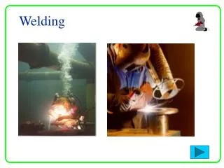
Welding • The process of permanently joining two or more metal parts, by melting both materials. The molten materials quickly cool, and the two metals are permanently bonded. Advantage: • Higher mechanical properties • Fixing stress cracks • Reinforcing weak joints • Cutting or shaping new parts
Equipments used in gas and oxy-acetylene welding processes Acetylene Steel cylinder High pressure acetylene is not stable so it dissolved in acetone, which has the ability to absorb a large volume of gas and release it as the pressure falls. 1 volume acetone-25 volume acetylene Pressure 1, 552 kN/m2 Danger of explosion-porous substance Oxygen Steel cylinder Contained in compressed form Supplied 3.4, 5 and 6.8 m3 capacities Mild steel-13, 660 kN/m2 Alloy steel-17, 240kN/m2 R. H. thread in valve
Welding gas mixture Fuel Gas Maximum Flame temperature with air (degree C) with oxygen (degree C) Acetylene 1 755 3 200 Butane 1 750 2 730 Coal gas 1 600 2 000 Hydrogen 1 700 2 300 Propane 1 750 2 500
Oxy-acetylene flame Neutral flame Oxidising flame Carburising flame www.twi.co.uk
Effect of welding on the structure Ref: Basic fabrication and welding enginering, F. J. M. Smith, LST
Temperature distribution during oxy-acetylene welding 10 mm thick mild steel
Arc welding The most common and economical method is AC arc welding
Arc • Highly luminous and intensely hot discharge of electricity between two electrodes • Discovered early 19th cent. by Sir Humphry Davy • High current and low voltage • When electrodes are parted, strong electric forces draw electrons from one electrode to the other, initiating the arc
Tungsten inert gas welding (TIG) Tungsten electrode-30000C Argon and Helium Filler material is added as in gas welding Shielding gases in arc welding Schematic of TIG
Metal inert gas welding (MIG) Consumable electrode Argon, Helium and Carbon Dioxide No filler materials Shielding gases in arc welding MIG weld area:
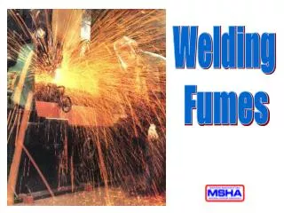
Risk involved in arc welding 1. Exposure to radiation 2. Flying sparks 3. Electric shock 4. Fumes 5. Damage to eyes 6. Burns
Safety • Make sure to work on a dry floor. • Wear thick rubber shoes and dry leather welding gloves. • Be sure to use insulated electrode holders. • Check to make sure that your equipment is all properly grounded. • Keep your work area properly ventilated to avoid inhaling any potentially toxic fumes. • Be on the look out for flying bits of melted metal. • Most importantly, be aware of any other people who are around you.
Magnetic Arc Welding • Arc is rotated around the weld line by the force which results from the interaction between the magnetic field and the current • CO2 or inert gas shielding is used
Steps in MIAB • Faces to be joined are brought together and internal magnetic coil is put in place • Welding current, magnetic coil system is put in place and shielding gas are turned on • Work pieces are retracted to a defined gap to produce the arc • Arc rotates about interface-melting faces to be joined • Faces are pressed together • Welding current, magnetic field and shielding gas are switched off
Magnetic Arc Welding MIAB Faster than arc fusion welding and conventional welding Used industrially Accurate-No further finishing machining operation are required Allows quality control MIAF Non-consumable electrode Suitable for welding of thin wall pipes or tubes certain pressed sheet fabrication
Friction welding -Friction heat caused by the motion of one surface against another enables plastic deformation and atomic diffusion at the interface -Used by the automotive industry for decades in the manufacture of a range of components -The weld is formed across the entire cross-sectional area of the interface in a single shot process
Advantages of friction welding • Narrow HAZ • Dissimilar metals can be joined • No fusion zone • Can be used under water • Very high reproducibility - an essential requirement for a mass production industry • Excellent weld quality, with none of the porosity that can arise in fusion welding • environmentally friendly, because no fumes or spatter are generated, and there is no arc glare or reflected laser beams with which to contend
Variations of friction welding • Rotary Friction Welding • Linear Friction Welding • Friction stir welding
Direct or continuous drive Pre-determined time of motion determined by the size and type of material
Inertia friction welding One of the work pieces is connected to a flywheel and the other is restrained from rotating Flywheel used to provide energy and is disengaged before the work pieces are pushed together Less drive power required than with direct drive welding
Linear friction welding ±1-3mm Frequency 25-125Hz Maximum axial force150kN
Steps in friction stir welding • A non-consumable rotating tool is pushed into the materials to be welded and then the central pin, or probe, followed by the shoulder, is brought into contact with the two parts to be joined. • The rotation of the tool heats up and plasticises the materials it is in contact with and, as the tool moves along the joint line, material from the front of the tool is swept around this plasticised annulus to the rear, so eliminating the interface.
Explosive Welding • Welding produced by explosively forcing one plate (or component) against the one to which it is to be joined at an approximate angle of incidence, known as the impact angle • Methods: 1. Inclined gap method 2. Parallel gap method In parallel gap method, detonation velocity should be equal to or less than the speed of sound in the metal being welded
Explosive Detonation velocity, m/s Explosives RDX (Cyclotrimethylene trinitramine, C3H6N6O6 8100 PETN (Pentaerythritol tetranitrate, C5H8N12O4) 8190 TNT (Trinitrotoluene, C7H5N3O6) 6600 Tetryl (Trinitrophenylmethylinitramine, C7H5O8N5) 7800 Lead azide (N6Pb) 5010 Detasheet 7020 Ammonium nitrate (NH4NO3) 2655
Inclined gap method • Various detonation speeds are possible with the inclined gap method • A jet is formed. The jet is a thin layer of metal stripped from the surfaces of both plates, which in turn exposes the uncontaminated metal surfaces which are then welded in the high pressure zone, known as stagnation point • Typically the weld surfaces are wavy • Weld is mainly solid state with small pockets of melted jet material (on the front and back slopes of the waves) • Some welding may also be enhanced by friction due to the difference in the velocity of the plates
Application of explosive welding • Cladding plates • Joining of pipes and tubes • Major areas of the use of this method are heat exchanger tube sheets and pressure vessels • Tube Plugging • Remote joining in hazardous environments • Joining of dissimilar metals - Aluminium to steel, Titanium alloys to Cr – Ni steel, Cu to stainless steel, Tungsten to Steel, etc. • Attaching cooling fins • Other applications are in chemical process vessels, ship building industry, cryogenic industry, etc.
Advantages of explosive welding • Can bond many dissimilar, normally unweldable metals. • Minimum fixturing/jigs. • Simplicity of the process. • Extremely large surfaces can be bonded. • Wide range of thicknesses can be explosively clad together. • No effect on parent properties. • Small quantity of explosive used.
Disadvantages of explosive welding 1. The metals must have high enough impact resistance, and ductility. 2. Noise and blast can require operator protection, vacuum chambers, buried in sand/water. 3. The use of explosives in industrial areas will be restricted by the noise and ground vibrations caused by the explosion. 4. The geometries welded must be simple – flat, cylindrical, conical. 5. Area should be cleaned and sound grounded for explosion 6. Licences are necessary to hold and use explosives
Ultrasonic welding • A solid state process for metal and plastics • Energy required comes in the form of mechanical vibrations • Most operates at 20, 30, 40 kHz • Weld is produced when the work pieces are clamped together between an anvil and a high frequency vibration probe (sonotrode) • Empirical relation for a ultrasonic welding: E=k(HT)3/2 Where, E = Electrical energy k = Constant for given welding system H = Vickers hardness T = Thickness of the work piece in contrast with the sonotrode
Types of ultrasonic welding Wedge-Reedmethod – where the transducer is coupled through a resonant bar Direct couple methods
Ultrasonic welding • Sonotrode induces lateral vibration and local movement between the frying surfaces • This tends to disrupt any surface oxide film present and also raises the temperature, extending an area of plastic flow, and a solid-phase type of pressure is formed • Morphology of the weld is similar to the friction weld
Variants: • Spot welding- elliptical “spots” • Ring welding – hollow sonotrode tip • Line welding – linear sonotrode tip • Continuous welding – Rotating wheel shaped sonotrode and a roller type of anvil Application: • Largest growth area for ultrasonic welding is micro miniature welding and micro joining in micro electric applications • Capable of joining very fine wires to electrical components