Download

1 / 21
210 likes | 301 Vues
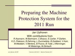
The Machine Protection System for the European XFEL E. Castro on behalf of the MPS team 08.10.2013. Outline. Requirements of the MPS MPS architecture and hardware Operation Schedule Summary. Requirements of the MPS.

E N D
The Machine Protection System for the European XFEL E. Castro on behalf of the MPS team 08.10.2013
Outline • Requirements of the MPS • MPS architecture and hardware • Operation • Schedule • Summary
Requirementsofthe MPS • Protect the accelerator from damage produced by the electron or photon beam • Help to control the radioactive activation of the components • Facilitate the handling of the machine and minimize the downtime: veto sections in the accelerator and dynamic limitation of beam power • Failsafe behavior:able to cope with SEUs, power cuts, cable breaks, … • Fast reaction time to minimize the number of bunches that are lost after detection of an alarm and before an action is taken The MPS should be highly reliable and “user-friendly”
Requirements: Reactiontimes LXFEL=3010 m (~10us) FXFEL=4.5 MHz Dumping beam in switchyard area would reduce the number of lost bunches inside SASE undulator sections: Upto100bunchescouldbelost beforelaserisblocked
MPS architecture (XSE) (XS1) • Issues: latencyofelectronicsandsignaltransportspeed additional lost bunches • Solution: • Distributed Master/Slave architecture: 2 Masters, 130 slaves • MPS canact on injectorlaserordump beam in caseof beam losses • Useofopticalfibers: fast signaltransmission, no EM interference • Mixed daisychain/startopology • FPGA-drivenlogic
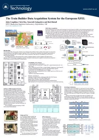
MPS hardware • MPS uses µTCA technology: Telecommunicationstandardadoptedby DESY. • compact, versatile and cost-efficient option for ultra-high speed analog and digital signal processing • The Masters andSlavesareequippedwith DAMC2 boards: MPS will profitfromitsextendeduse in XFEL • The RTM boardfeedsthealarmsignalstothe DAMC2. DAMC2 MPS RS422 RTM 45 in Dosi-Mon card 4 I/O optical connections 7 out FPGA µTCA in DESY: http://mtca.desy.de/index_eng.html
Overall features • Scalability: system can grow • Every slave holds all information of all prior connected slaves • Slaves can hold one dosimetry board • Each input alarm/output action is recorded by DOOCS • Low latencies: • Interfaces: • Master-Slaves communication via 4 serial in/out optical ports • To Timing System via the µTCA backplane • Signals from/to external systems via RS422 lines Measurementsdone in August 2013. An improvement in a factor 3 isexpected (plus 5ns/m) 82 ns MASTER Alarms OUT 780 ns MASTER SLAVE Alarms IN 1400 ns SLAVE SLAVE MASTER
Operation: tasks • Collectthe status signals and alarms from the output of subsystems in the accelerator • In case of alarms, evaluate the response using internal alarm-response matrices • Constantly inform the Timing System about maximum allowed bunches and available accelerator sections • In case of a critical situation, immediately stopthe beam by directly acting on the laser or dump kicker • Forwardingcertain signals to other subsystems (e.g. Cryo OK signal)
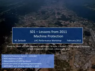
Operation: datastructures The two Master boards collect the information about the status of the devices connected to theslaves and generate: • Beam Modes: amount of bunches allowed in accelerator sections • Section Patterns: beam permissions in several accelerator subsections Beam Modes Section Patterns
Operation: interfacewith Timing System • Beam Modes and Section Pattern are forwarded to the Timing System • Together with the requested bunch patterns from the operator, the Timing System will generate the table of allowed Bunch Patterns foreachmacro-pulse (10Hz) (Bunchpattern: 32 bitswithinfoaboutbunchchargeandpathtofollow in XFEL) MPS and Timing System areasynchronous MPS and Timing masters in the same crate MPS and Timing slaves in diagnosticscratesalong XFEL Communication allows time stamping Interface betweenthe MPS and Timing System
Operation: systemsconnectedtothe MPS Systems connectedtothe MPS The MPS receives ~2000 statussignalsfromsystems in the XFEL It will reactinmediatelytoalarmsfollowing a predefinedreactionprotocol: • Establishing a newinjectionschemefornextmacro-pulse (slowreaction) • In caseofdangerousoperatingconditions, shutting down laserordumping beam directlywithin a macro-pulse (fast reaction) MPS outputsignals
Operation: interactionwith XFEL subsystems All ofthepersonsresponsibleforthe XFEL equipmenthavebeencontactedfortheelaborationofthe CDR. Followingpointswereagreed: • Each subsystem will providethealarmsignal in RS422 standard • Minimum durationofthesignalis 100ns • Itshouldbepossibletomaskalarmstopreventunnecessary XFEL downtime: • Internallybyexperts in thesubsystems • Externallyfromthe MPS • Personnal InterlockandManual Beam Off canbridgethe MPS controlandstopthe beam ifneeded
Operation: MPS alarmresponse Takingintoaccountthelocationofthealarmandthesource, the MPS builds a possiblereactionscheme. Example: vacuumalarmalong XFEL Example: alarms in thedumps
Operation: safetyofbeam transportandexperiments The equipmentprotectionsystemofphoton beam linesandexperimentsisintegrated in themachine MPS: • Provides: signalsfrom X-ray BLMs anddesired Beam Mode • Safetyhighlydependent on the MPS Beam Mode 5 experiments, different beam requirements but operatingwith same e- beam Challenge: to eventually decouple 15 experiments running in 5 SASE beamlines.
Operation: Organigramofresponsibilities • Each ofthemonitorsconnectedtothe MPS areresponsibleforthetuningoftheiroperationconditions(numberofbunchesthatcanwithstand, thresholds,…) anddetectalarmsproperly. • Systems such as LLRF, photonbeamlinesareequippedwith interlock systemstoensuretheprotectionofequipment. The MPS receivestheir interlock signal. • The MPS isresponsibleofreactingtothealarms.
Operation: MPS failsafeoperation The failsafe operation of the MPS system does not rely on hardware redundancies. The correct communication between masters and slaves is guaranteed by special algorithms built on counters, parity bit, detection of broken lines, … However, critical connections (to laser controller or dump) can be set up redundantly. A cable break or short circuit in RS422 lines will be detected and reported as a normal interlock signal without specifying the type. Subsystems connected to MPS are responsible to provide a reliable signal.
Operation: Configurationandvisualization Configuration: Masters and slaves boards are configurable through JDDD displays connected to DOOCS MPS servers. After a power cut or hardware-reset the static configuration (reaction to alarms) has to be uploaded from DOOCS into the FPGA Visualization: The status of the MPS will be displayed with JDDD GUIs, for experts and operators. Alarm analysisandhandling Every MPS board has an alarm logging and a time stamp for every event. The post-mortem analysis will be done using the alarm logging and time stamps provided by the subsystems. The handling of alarms will be done automatically by the MPS, or manually by the operator. MPS-board DAMC2 Dosi-Mon FMC-card MPS-server DOOCS Expert config panel JDDD Expert operation panel JDDD Server tasks: Synchronizestaticconfiguration Providestatussignalstodisplays Log events config-file Operator panel
Operation: MPS configuration MPS configurationpanelfor FLASH
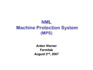
Operation: MPS visualization Info per MPS-slave and master State of diagnose inputs State of digital outputs Proposed Section Pattern and Beam Modes Board events with time stamps MPS expert viewfor FLASH
Schedule So far, thescheduleofthe MPS fitsintothe XFEL timetable
Summary • The development of the MPS for the XFEL is ongoing as planned • Each of the suppliers of status signals to the MPS was contacted to clarify their integration into the final design of the system. • A rough plot of the reaction protocol of the MPS to the alarms was elaborated. • The first installation of the MPS for the XFEL injector was successfully done • We will gain operation experience at FLASH II before the startup of XFEL More info in the MPS CDR (EDMS number D00000003387601)