Download
1 / 23
230 likes | 325 Vues
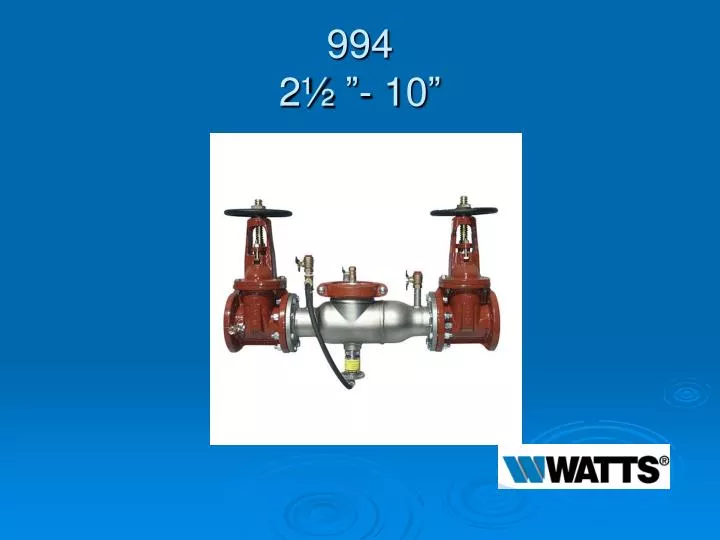
994 2½ ”- 10”. Modification Overview. Production for the 994 began in 1999 and is current. Single Access Cover Removal. Cover is secured by a grooved coupling. Cover has no spring load. Check Valve Removal. Check valve modules called “Cam Checks”. Checks are o-ring sealed.

E N D
Modification Overview • Production for the 994 began in 1999 and is current.
Single Access Cover Removal • Cover is secured by a grooved coupling. • Cover has no spring load.
Check Valve Removal • Check valve modules called “Cam Checks”. • Checks are o-ring sealed. • 21/2”-6” Cam Checks are threaded into body. • #1 Check must be removed before #2 can be removed. • 8-10” Checks are simply bolted into body.
Check Valve Removal • 21/2-6” cam checks unscrew counterclockwise by hand “if possible”. *Do not use cam arm as a handle to unscrew.
Check Valve Removal • 21/2-6” Cam Checks. • If too tight, place a drift punch or solid rod (long screwdriver) in one of the holes on the outer edge of the check module. • Tap with hammer in correct direction (counterclockwise) to loosen.
Check Valve Removal Notes • 21/2-6” Cam Checks. • There are “special tools” available to help remove check modules.
Check Seat Removal • Check seats are part of each module and can not be removed. • If the seat is damaged, the complete check module will need to be replaced.
Check Disc Inspection 21/2”- 6” • 21/2”-4” first check and all 6” sizes. • Locate the stud on the outlet flange of the assembly. • Place the cam arm hole on the stud and open the check valve so that the cam arm rests between the roller and clapper.
Check Disc Inspection 21/2”-6” • 21/2 - 4” second checks only. • Lift the cam arm and hold in open position. *Raise the clapper so that the end of the cam arm rests between the roller and clapper.
Check Disc Inspection 8”-10” • 8-10” first check. • Place two 3/8” X 14” all thread rod through the two holes of the spring retaining plate. • Screw the rods into the disc holder about ½”. • Secure both rods with 3/8” nuts.
Check Disc Inspection 8”-10” • 8-10” first check. • Tighten both nuts evenly to compress spring. • Compress the spring until the clapper has moved about 1” from seat and inspect. • To remove rod, loosen nuts evenly – be careful not to unscrew rod.
Check Disc Inspection 8”-10” • 8-10” second check • Using a 3/8” nut driver or a piece of small diameter pipe, place on the end of the torsion spring and move away from and around the retaining bracket. • This will free the cam arm and clapper.
Check Valve Reassembly Notes • Lubricate check o-ring. • Reassemble check modules in reverse order. • Lubricate outside edge of groove coupler gasket.
Relief Valve Removal • RV assembly is threaded onto body and o-ring sealed. • Disconnect RV Hose. • Unscrew complete RV assembly from the main body. **Do not place wrench on RV housing. • Place wrench on flange and cover only.
Relief Valve Removal • Remove cover bolts. • Remove piston and sleeve by sliding them out through the flange side of the RV housing.
RV Seat Removal • The RV seat is a machined part of the RV housing. • To replace the seat, you must replace the housing.
Relief Valve Disassembly • Remove sleeve from piston assembly. • The piston assembly is spring loaded. • Hold the piston firmly in one hand and unscrew the hex head bolt.
RV Disc Replacement • Replace the RV disc in the disc holder. • Replace the o-rings on the hex head bolt.
RV Diaphragm Replacement • Reassemble the disc holder and spring to the diaphragm / piston assembly. • Slide sleeve over diaphragm. • Position the bead of the diaphragm over the edge of the sleeve.
RV Diaphragm Replacement • While holding the sleeve in one hand, place the bolt end of the assembly on a flat surface. • Using the other hand, cup the palm slightly over the diaphragm to form an air trap.
RV Diaphragm Replacement • Rapidly slap the diaphragm down over the piston assembly and inside the sleeve. **If the diaphragm is wrinkled, then it is not in the correct position. • Repeat this step if necessary.
Relief Valve Reassembly Notes • Slide the piston assembly and sleeve into the housing in reverse order.