Download
1 / 78
780 likes | 958 Vues
Jochen Blumberger University College London Trieste, 23.05.2014. Simulation of Charge T ransport in Oxides and Organic Semiconducting Materials. Workshop on Materials Challenges in Devices for Fuel Solar Production and Employment. II. CT in oxide materials. Overview.

E N D
Jochen Blumberger University College London Trieste, 23.05.2014 Simulation of Charge Transport in Oxides and Organic Semiconducting Materials Workshop on Materials Challenges in Devices for Fuel Solar Production and Employment
II. CT in oxide materials Overview I. Theoretical background Food III. CT in organic solar cell materials IV. CT in bacterial nanowires Electrode e- Microbe Food
Photoelectrochemical cell good charge transport essential for high efficiency oxide e-
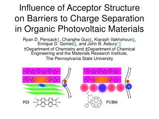
Organic photovoltaic cell good charge transport essential for high efficiency e- Clarke and Durrant, Chem Rev. (2010)
Mediatorless microbial fuel cell Electrode e- Microbe good charge transport essential for high efficiency Food Ishii, S. et al. Appl. Environ. Microbiol. 71, 7838 (2006). Summers, Z. M. et al. Science 330, 1413 (2010).
Why computation ? Nature of charge carrier (localised/delocalised) Mechanism of charge transport (band/hopping/wavepacket) Atomistic interpretation of measured charge mobilities, I-V curves NanoStructure-property relationships
Overview • I. Theoretical Background • II. Electron tunneling between O-vacancies in MgO • III. Electron transport in fullerenes • IV. Electron transport in bacterial nanowires
Which theory is adequate? Charge mobility electron-phonon coupling or reorganisation energy or trapping energy
Which theory is adequate? metals band theory Charge mobility redox in solution redox proteins Small polaron hopping ET theories (Marcus) electron-phonon coupling or reorganisation energy or trapping energy
Which theory is adequate? metals holes/e- in oxides holes/e- inorganic semiconductors band theory ? Charge mobility redox in solution redox proteins Small polaron hopping ET theories (Marcus) electron-phonon coupling or reorganisation energy or trapping energy
Electron transfer theory (Thermally activated polaron hopping) e- e- initial diabatic state final diabatic state
Diabatic and adiabatic electronic states Q reaction coordinate λ reorganization energy Hab electronic coupling matrix element initial diabatic state e- e- final diabatic state adiabatic ground & 1st excited ET state
Diabatic and adiabatic electronic states Landau-Zener theory Transition state theory Nuclear tunneling e- e-
Martin Karplus (1963) (?), Arieh Warshel (1993), Troy Van Voorhis (2005), John Tully (2008),… Diabatic states from constrained DFT (CDFT) Idea: - Construct Hamiltonian in diabatic = charge localized basis -Create charge localized states by adding an external potential to Hamiltonian =
Q. Wu and T. van Voorhis, Phys. Rev. A72, 024502 (2005) Charge constrained DFT (CDFT) 1. Define donor, acceptor and external potential w(r)
Q. Wu and T. van Voorhis, Phys. Rev. A72, 024502 (2005) Charge constrained DFT (CDFT) 1. Define donor, acceptor and external potential w(r) 2. Add Vw(r) to KS-equation and vary V so that charge constraint is fulfilled.
Q. Wu and T. van Voorhis, Phys. Rev. A72, 024502 (2005) Charge constrained DFT (CDFT) 1. Define donor, acceptor and external potential w(r) 2. Add Vw(r) to KS-equation and vary V so that charge constraint is fulfilled. e- diabatic state A ψA, EA = FA-VAN e- diabatic state B ψB, EB = FB-VBN
Q Wu and T Van Voorhis, Phys. Rev. A72, 024502 (2005) Charge constrained DFT (CDFT) 1. Define donor, acceptor and external potential w(r) e- diabatic state A ψA, EA = FA-VAN e- diabatic state B ψB, EB = FB-VBN
H. Oberhofer, JB, J. Chem. Phys.131, 064101 (2009) H. Oberhofer, JB, J. Chem. Phys. 133, 244105 (2010) CDFT Implementation in the CPMD code • CDFT weight function for charge constraint: • where ρi are promolecular atomic densities (pseudo AO, Slater, Gaussians) • CDFT wavefunction optimisation, geometry optimisation and BOMD • GGA, hybrid and range separated hybrid functionals (with new HFX parallelisation) • Troullier-Martins or Goedecker-Hutter pseudo potentials for core electrons • Available in CPMD Version 3.15.1 (thanks to M. Boero and T. Laino)
Benchmarking CDFT electronic couplings (Hab):The HAB11 database A. Kubas, F. Hoffmann, A. Heck, H. Oberhofer, M. Elstner JB, J. Chem. Phys.140, 104105 (2014).
A. Kubas, F. Hoffmann, A. Heck, H. Oberhofer, M. Elstner JB, J. Chem. Phys.140, 104105 (2014). HabCDFT error wrt MRCI+Q/NEVPT2 • Relatively small dependence on %HFX • 25-50% HFX gives excellent accuracy
Overview • I. Theoretical Background • II. Electron tunneling between O-vacancies in MgO • III. Electron transport in fullerenes • IV. Electron transport in bacterial nanowires
Electron tunneling between F+-F0 centres in MgO F+ F0 positively charged oxygen vacancy neutral oxygen vacancy
K. P. McKenna, JB Phys. Rev B. 86, 245110 (2012). Initial diabatic state from CDFT Isosurface of spin density, PBE0 (CPMD code):
K. P. McKenna, JB Phys. Rev B. 86, 245110 (2012). Initial diabatic state from CDFT Isosurface of spin density, PBE0 (CPMD code):
K. P. McKenna, JB Phys. Rev B. 86, 245110 (2012). Final diabatic state from CDFT Isosurface of spin density, PBE0 (CPMD code):
K. P. McKenna, JB Phys. Rev B. 86, 245110 (2012). Electronic coupling • CDFT calculation with PBE0 for • F-centres along 100, 110, 111, 211 and 310 crystallographic directions • distance between F-centres ranging from 3 to 16 Angstroms
JB, K. P. McKenna, Phys. Chem. Chem. Phys. 15, 2184 (2013). Hab CDFTfor hole transfer in MgO PBE with different %ages of Hartree-Fock exchange (HFX): 15 5 10 defect separation (Angstroms) • Strong dependence on % HFX
JB, K. P. McKenna, Phys. Chem. Chem. Phys. 15, 2184 (2013). Coupling decay constant b versus band gap Eg Eg: band gap of MgO PBE + x % HFX 75% 50% 100% 25% 0%
Square barrier tunneling model Exact solution of Schroedinger equation: Use functional that gets band gap right (PBE0 i.e. 25%HFX)
V. Weber, T. Laino, A. Curioni (IBM Zurich) http://cpmd.org/the-code/performance-and-scale-out Parallelisation of HFX in CPMD Mg80O78+ PBE0 hfx parallelized PBE0 PBE
JB, K. P. McKenna, Phys. Chem. Chem. Phys. 15, 2184 (2013). Accounting for finite size effects on electronic coupling
JB, K. P. McKenna, Phys. Chem. Chem. Phys. 15, 2184 (2013). Accounting for finite size effects on electronic coupling
K. P. McKenna, JB Phys. Rev B. 86, 245110 (2012). Electronic coupling versus defect separation CDFT, PBE0, for MgO 100, 110, 111, 211 and 310 crystallographic directions • Overall approximately exponential and isotropic decay
K. P. McKenna, JB Phys. Rev B. 86, 245110 (2012). Reorganization energy versus defect separation CDFT, PBE0, for MgO 100, 110, 111, 211 and 310 crystallographic directions • long range: Marcus like l = const – 1/d • short range: non-Marcus due to large distortions of e--Mg2+ distances
K. P. McKenna, JB Phys. Rev B. 86,45110 (2012). Hole transfer rates between F-center defects in MgO 13 12 11 10 9 log (kET/s-1) 8 7 6 hello hello hello 5 4 0 2 4 6 8 10 12 14 16 18 20 distance between F centers (Angstroms)
Three ET regimes Hab > 3/8 λ Hab << λ Hab < 3/8 λ delocalized carrier “non-adiabatic ET” “adiabatic ET” no ET rate defined
Rates & Transport regimes 13 12 K. P. McKenna, JB Phys. Rev B. 86, 245110 (2012). 11 10 no polaron no rate 9 log (kET/s-1) 8 hole hopping 7 crossover incoherent coherent transport hole hopping 6 5 4 0 2 4 6 8 10 12 14 16 18 20 distance between F centers (Angstroms)
Overview • I. Theoretical Background • II. Electron tunneling between O-vacancies in MgO • III. Electron transport in fullerenes • IV. Electron transport in bacterial nanowires
Electron transport in fullerenes Clarke and Durrant, Chem Rev. (2010) e- exciton dissociation efficiency electron mobility nanoscale/mesoscale structure
Phenyl-C61-Butyric acid Methyl ester (PCBM) monoclinic w. solvent triclinic w. solvent hexagonal (no X-ray) distorted bcc (model) Rispens et al. Chem Commun 2116, (2003). Dabirian et al. PCCP 12, 4473 (2010). Kim et al. ACS Nano 3, 2557 (2009).
G. Paterno, J. Spencer, JB, F. Cacialli and co-workers, J. Mater. Chem. C (2013) First solvent-free PCBM single crystal monoclinic 4 PCBM/unit cell See also Casalegno et al. Chem. Commun. 49, 4525 (2013) obtained by slow drying from chlorobenzene
G. Paterno, J. Spencer, JB, F. Cacialli and co-workers, J. Mater. Chem. C (2013) First solvent-free PCBM single crystal
First solvent-free PCBM single crystal G. Paterno, J. Spencer, JB, F. Cacialli and co-workers, J. Mater. Chem. C (2013) very good agreement with experimental X-ray structure
F. Gajdos, H. Oberhofer, M. Dupuis, JB J. Phys. Chem. Lett. 4, 1012 (2013). Electronic couplings vs distance in PCBM crystals I (Gajdos)
F. Gajdos, H. Oberhofer, M. Dupuis, JB J. Phys. Chem. Lett. 4, 1012 (2013). Electronic couplings vs distance in PCBM crystals constructive orbital overlap destructive orbital overlap
is currently the state-of-the-art, used by many groups: Bredas, Nelson, Andrienko,… Polaron hopping field e- time calculate Hab, l, DE for all possible hops hopping rate kETfor all possible hops
is currently the state-of-the-art, used by many groups: Bredas, Nelson, Andrienko,… Polaron hopping field e- Kinetic Monte Carlo time experiment calculate Hab, l, DE for all possible hops hopping rate kETfor all possible hops mobility factor of 6 too large not bad….
is currently the state-of-the-art, used by many groups: Bredas, Nelson, Andrienko,… Polaron hopping field e- Kinetic Monte Carlo time experiment calculate Hab, l, DE for all possible hops hopping rate kETfor all possible hops mobility factor of 6 too large not bad….
Polaron does not exist |HAB| = up to 150 meV λ = 150 meV |HAB| > 3/8 λ • no barrier, ET rate not defined • (though one can still insert into the rate equation and get some number)