Download
1 / 17
170 likes | 176 Vues
CALICE DAQ Developments. DAQ overview DIF functionality and implementation EUDET Prototype development path. DAQ architecture. Slab hosts VFE chips DIF connected to Slab LDA servicing DIFs LDAs read out by ODR PC hosts ODR, through PCIexpress C&C routes clock, controls.

E N D
CALICE DAQ Developments DAQ overview DIF functionality and implementation EUDET Prototype development path 12-09-2007 CALICE meeting, Prague
DAQ architecture • Slab hosts VFE chips • DIF connected to Slab • LDA servicing DIFs • LDAs read out by ODR • PC hosts ODR, through PCIexpress • C&C routes clock, controls 12-09-2007 CALICE meeting, Prague
ODR and Data Rates • ODR is a commercial FPGA board with PCIe interface (Virtex4-FX100, PCIe 8x, etc.) • Custom firm- and software • DMA driver pulls data off the onboard RAM, writes to disk • Performance studies & optimisation 12-09-2007 CALICE meeting, Prague
Clock & Controls Distribution • C&C unit provides machine clock and fast signals to ODR, LDA (and DIF?) • Clock jitter requirement seems not outrageous (at the moment) • Fast Controls: encoded through the LDA-DIF link • Low-latency fast signals: distributed ‘directly’ 12-09-2007 CALICE meeting, Prague
LDA and link to ODR • Enterpoint Xilinx Spartan3 based dev. board • RAM & lots of I/O (including PCI) 1st Prototype is again a commercial FPGA board with custom firmware and hardware add-ons: • Gbit ethernet and Glink Rx/Tx for ODR link -probably optical • Many links towards DIFs 12-09-2007 CALICE meeting, Prague
LDA-DIF link LDA-DIF link: • Serial link running at multiple of machine clock • 50Mbps (raw) bandwidth minimum • robust encoding (8B/10B or alike) • anticipating 8…16 DIFs on an LDA, bandwidth permitting • LDAs serve even/odd DIFs for redundancy 12-09-2007 CALICE meeting, Prague
LDA-DIF physical interface clock data control spare data spare control LDA-DIF link physical form factor: • Differential signals on shielded twisted pairs • Few single-ended control lines • HDMI connectors and cabling: high quality, commercially available 12-09-2007 CALICE meeting, Prague
DIF-DIF link • Redundancy against loss of LDA link • Provides differential signals: • Clock in both directions • Data and Control connections • Two spares: one each direction • Plus two single-ended control lines • Single LDA-DIF link bandwidth sufficiently large for data of two DIFs 12-09-2007 CALICE meeting, Prague
Draft DIF block diagram not definitive Lots of controls…. 12-09-2007 CALICE meeting, Prague
DIF Functionality • Receive, regenerate and distribute clocks • Receive, buffer, package and send data from VFE to LDA • Receive and decode incoming commands and issue corresponding signals • Control the DIF-DIF redundancy connection • Receive, decode and distribute slow control commands • Control power pulsing and provide watchdog functionality • Provide an USB interface for stand-alone running and debugging • …..on top of that: all the things we did not think of so far 12-09-2007 CALICE meeting, Prague
DIF implementation • The Slab is an integral part of the detector • The LDA and ODR are transparent wrt detector type • The DIF and its interface to the slab is detector-specific • Large parts of the DIF firmware can/should/must be generalised • DIF hardware should support firmware to profit from common developments • DIF working group to address common problems and share knowledge, experience, and VHDL code 12-09-2007 CALICE meeting, Prague
Opportunity to memorise the acronyms: 12-09-2007 CALICE meeting, Prague
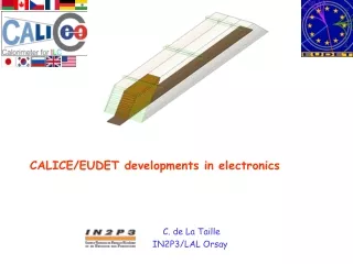
The EUDET prototype • Full stack: 15 slabs, instrumented on both sides • As close to CALICE technology as reasonably possible 12-09-2007 CALICE meeting, Prague
Prototype development NOW 2008 2009 HaRDROC chip v1 Testbeam DAQ HaRDROC chip v2 New DAQ v1 EUDET proto: detector + DAQ 12-09-2007 CALICE meeting, Prague
Technology prototype for physics results EUDET module is quite a large and complex object. Keep future production in mind: • large objects are assemblies of smaller objects • develop testable objects Many technology options require even more R&D: • power consumption • data rate: speed vs. power • noise • etc. 12-09-2007 CALICE meeting, Prague
R&D for the EUDET prototype • Proto-slab: • FPGA for VFEs • provisional ‘DIF’ for ECAL • Tests of signal distribution along long PCB lines: signal deterioration, termination options, speed, etc. • Identification of possible issues with many (pseudo)VFE chips on long transmission paths • Familiarise with VFE readout architecture 12-09-2007 CALICE meeting, Prague
R&D for the EUDET prototype More to come….. …but let’s look at the DIF design first 12-09-2007 CALICE meeting, Prague