Download
1 / 14
140 likes | 156 Vues
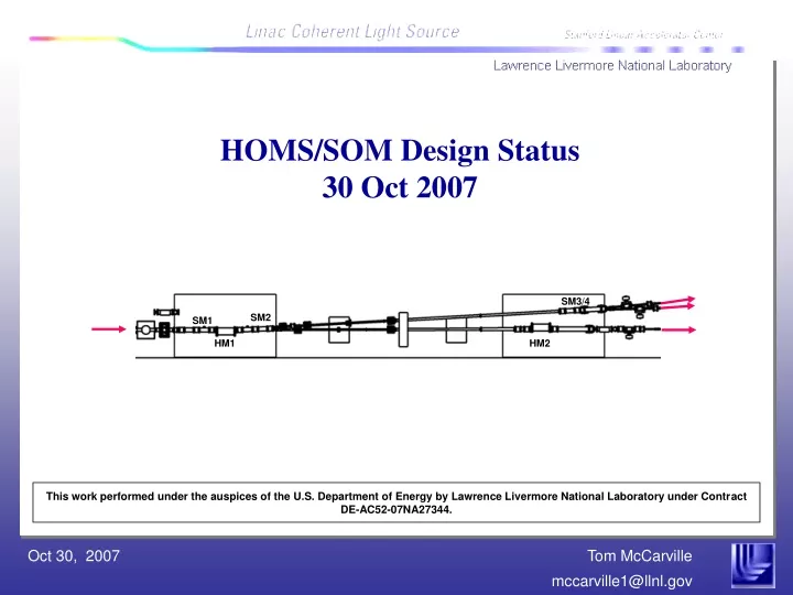
SM3/4. SM2. SM1. HM1. HM2. HOMS/SOM Design Status 30 Oct 2007. This work performed under the auspices of the U.S. Department of Energy by Lawrence Livermore National Laboratory under Contract DE-AC52-07NA27344.

E N D
SM3/4 SM2 SM1 HM1 HM2 HOMS/SOM Design Status30 Oct 2007 This work performed under the auspices of the U.S. Department of Energy by Lawrence Livermore National Laboratory under Contract DE-AC52-07NA27344.
Preliminary design/test of HOMS & SOMS integrated mirror systems is nearly complete 1.4 m Risk levels: Well established solutions & practices Moderate effort to demonstrate Significant effort to demonstrate • High risk areas receiving special attention are the subject of this talk
Y (vert.) Z X HOMS & SOMS share the same basic design Mirror mount assembly Vacuum Chamber Tunable Z force 2 fixed X forces & constraints Rotation spindle & drive cam Translation slide 3 fixed Y forces & constraints Z constraint 6-axis strut assembly Support Pedestal Y constraint flexure B4C chin guard • The HOMS design incorporates additional features to achieve - higher pointing resolution - tighter figure control
SOMS HOMS 250 mm 450 mm 30 mm 430 x 15 mm2 175 x 10 mm2 50 mm 30 mm 50 mm Mirror figure error must limit the beam divergence change to < 10% • Figure requirements and allocation to contributing factors are expressed in nm, peak/valley << requirement < requirement > requirement Sagittal axis Tangential axis
Figure error budgets were established by finite element analysis of the mirror and mount • Conclusions from finite element calculations of assembled mirror & mount: • Coating stress + fabrication errors dominate the figure error • Net curvature is primarily sphere • Spherical errors can be corrected by bending the mirror HOMS • Contribution • Coating • Mounting • Thermal • Gravity Total (convex) • Changes since HOMS PDR: • Mirror holes relocated to better balance gravity load • Refined modeling boundary conditions
HOMS tangential figure will be adjusted during operation by bending the mirror • An axial force & constraint are applied near the back of the mirror • 200 nm concave pre-figure will unbent during assembly on an interferometer • - bending will be applied before securing vertical hold down springs • - the model shows aspheric curvature near free corners Mirror bonded to mounting pads 4.4 lb Unbonded (vertical springs loose) 3.7 lb
The HOMS mirror assembly accommodates real-time figure control • Concave pre-figure removed by applying force to the anvil while observing with an interferometer • Mirror assembly is installed into the vacuum chamber & adjustment spring is attached • Figure is remotely adjusted by pull/push on the adjustment spring • - spring travel range provides high resolution, high thermal stability Anvil Adjustment spring Shaft & bellows Motorized micrometer Manual Pre-load Adjustment
450 mm Measured area: 270 x 15 mm2 Bender performance is being validated on the HOM prototype: a silica mirror on Invar mount • Measured deflection is in reasonable agreement with the finite-element model • Aspheric residual from bending is within our measurement noise floor Calculated: 2.7 lb FOV Measured on 12” interferometer 5nm Turbulence scale Vibration scale +/- 1.5 nm uncertainty 0 15mm 270mm 0
X (hor.) Z Y (vert.) HOMS mirror pointing stability requirements are very challenging • Rotation increments must in step the beam within 10% of its diameter at the experiment stations - long term stability should be even less NEH SM3/4 Plan view (not to scale) 30 m SM2 FEH SM1 HM2 HM1 300 m
The HOMS rotation resolution requirement has been demonstrated Data for a 1 mm offset cam, 2500:1 harmonic drive, in 10 nr increments Rotation spindle - flexure type • Stepper motor • 1000 step/rev • Harmonic drive • 2500:1 for HOMS • Cam assembly • 0.7 mm offset Pusher - 2 axis flexure • Two capacitance sensors with 0.5 nm resolution measure angle change • - they are fast enough (5 kHz) to demonstrate natural frequencies are wo>>100 Hz
A tiered approach is taken to evaluate pointing stability 1st tier: Eliminate thermal jitter with periods < 1 hr - any air tight enclosure will suffice - long period temperature oscillations penetrate easily - rotation jitter closely follows temperature - a long period oscillation remains, but is it rotation or sensor drift? Insulation Inside air Outside air All carbon steel components Insulation No Insulation
Sensor drift makes it difficult to trust long term measured trends • Sensors are placed in a static gage block to measure temperature correction • Uncorrelated drift is also observed, corrupting long term data. • Presently investigating how to improve this Sensor calibration block 60 mV drift Zero Drift in nrad
Additional measures being investigated to control rotation drift: • 2nd tier: add a thermally compensating material to the rotation linkage • - requires accurate long term rotation measurements • 3rd tier: use water tempered to limit excursions inside the enclosure • < +/- 0.1 C • - compact air cooled chillers are readily available • 4th tier: adjust rotation real time by measuring x-ray beam drift • Another alternative: make everything out of Invar instead of stainless steel – not presently being pursued
Summary of key opto-mechanical design issues – figure and pointing corrections are both metrology limited • The contributing factors to figure error are becoming well understood • - mounting, thermal, and gravity induced errors are small: coating & fabrication errors dominate • - errors < 10-20 nm are not easily measured for off-line correction • - real time correction during operation is advisable for HOMS • Long term pointing stability is under investigation • - insulation eliminates rotation fluctuations with < 1 hr period • - passive compensation requires nm resolution sensors with long term stability: not yet identified • - tempered water will limit enclosure variations < +/- 0.1 C • - real time pointing corrections are always an option (last resort)