Download
1 / 33
530 likes | 1.53k Vues
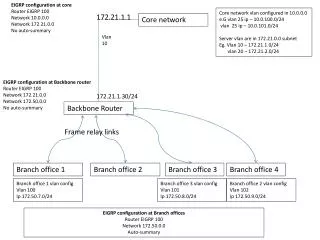
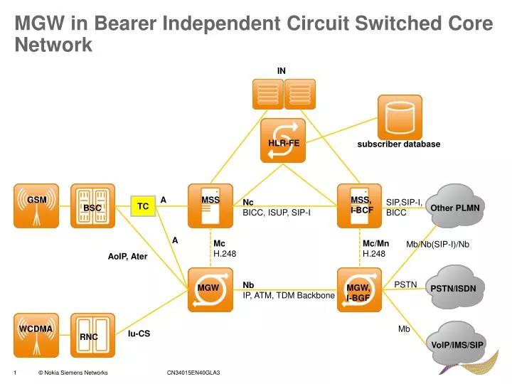
MGW in Bearer Independent Circuit Switched Core Network. IN. HLR-FE. MSS, I-BCF. MSS. GSM. A. Nc BICC, ISUP, SIP-I. SIP,SIP-I, BICC. TC. BSC. Other PLMN. A. Mc H.248. Mc/Mn H.248. Mb/Nb(SIP-I)/Nb. MGW, I-BGF. MGW. AoIP, Ater. subscriber database. PSTN. Nb

E N D
MGW in Bearer Independent Circuit Switched Core Network IN HLR-FE MSS, I-BCF MSS GSM A Nc BICC, ISUP, SIP-I SIP,SIP-I, BICC TC BSC Other PLMN A Mc H.248 Mc/Mn H.248 Mb/Nb(SIP-I)/Nb MGW, I-BGF MGW AoIP, Ater subscriber database PSTN Nb IP, ATM, TDM Backbone PSTN/ISDN WCDMA Mb Iu-CS RNC VoIP/IMS/SIP
Functional Units (Nodes) in Open MGW FI&BI between shelves IP signaling TCU Hub TCU TCU Hub TCU IPNI1 IP/GE AMCCarrier AMCCarrier IP User Plane TCU TCU IPNI10 IP/10GE ISU TDM User Plane and signalling TCU BI TDMSNI TCU CLA O&M FI ADDF TCU RTM TDM E1/T1 TDM STM-1/OC3 RTM Sync. clock RTM
Control and Administrative Computer Unit (CACU) • Purpose: CACU controls the ATM switch fabrics and establishes connections for calls. • It’s ATM switching management functions comprises: • Establishment of both internal and external connections via the SFU, including ATM circuit hunting and address analysis. • Management and control of the SFU, A2SU, and MXU • Transmission resource management • Redundancy: 2N • PIU:CCP18-C (Intel Pentium M) • Interface: ATM interface to MXU • Max. number of units in subracks:2 CCP18-C
Central Memory (CM) • Purpose: CM serves as the central data storage and distribution facility. • It also handles the centralised part of the common channel signalling, for example, digit analysis. • Redundancy: 2N • PIU:CCP18-C (Intel Pentium M) • Interface: ATM interface to MXU • Max. number of units in subracks:2 CCP18-C
Interface Control and Signaling Unit (ISU) • Purpose: ISU is responsible for signalling gateway functions between access networks and MSC Server. • Its task include the following: • Process MTP and SCCP of both narrowband and wideband SS7 signalling. • Messange handling and processing functions related to the signalling channel connected to it. • Redundancy: N+1 • PIU:CCP18-C (Intel Pentium M) • Interface: ATM interface to MXU • Max. number of units in subracks:18 (New deliveries in MGW U5.0) CCP18-C
Voice Announcement Unit (VANU) • Purpose: VANU controls the announcement function of MGW. • It stores the individual speech samples, constructs complete announcements from them and sends them to the DSP units for further processing. • Redundancy: None • PIU:CCP18-C (Intel Pentium M) • Interface: ATM interface to MXU • Max. number of units in subracks:2 CCP18-C
Switching Unit (SWU) • Purpose: SWU is a LAN/Ethernet Switching function, which provides LAN/Ethernet interfaces for: • Control plane (H.248 and M3UA) • O&M signalling (e.g. towards NetAct) • ESA40-A has four Gb Ethernet ports. • This allows the separation of control plane and O&M traffic to dedicated ports within one pair. • ESA40-A supports L3 connectivity solution. • Redundancy: SN+ • PIU:ESA40-A (LAN/Ethernet switch) • Interface: LAN/Ethernet to OMU, ISU and site LAN • Max. number of units in subracks: 6 ESA40-A
Operation and Maintenance Unit (OMU) • Purpose: OMU handles all the MGW’s crucial upper-layer system maintenance functions, such as: • Hardware configuration management • Hardware Management System (HMS) supervision • Associated centralised recovery functions. • In the event of fault, the OMU automatically activates appropriate recovery and diagnostics procedures within the MGW. • Redundancy: 2N • PIU:CCP18-A (Intel Pentium M) • Interface: ATM interface to MXU, LAN/Ethernet via ESA40-A, Duplicated SCSI, Service Terminal interface, Duplicated HMS interface • Max. number of units in subracks:2 CCP18-A
OMU’s storage devices • Purpose: OMU has two dedicated hard disk units which serve as a redundant storage for: • The entire system software • The event buffer for intermediate storing of alarms • The radio network configuration files. • Backup copies are made onto a USB memory stick that can be connected to the CCP18-A PIU’s front plate. • Redundancy: 2N • PIU:HDS-B • Interface: SCSI (Small Computer System Interface) • Max. number of units in subracks:2 HDS-B
Transcoding Unit (TCU) • Purpose: TCU includes a number of signal processors whose main functions are: • Transcoding • Signal level control • Discontinuous transmission • All DSPs of the unit can be freely allocated within the MGW. • Redundancy: SN+ • PIU:CDSP-DT • Interface: ATM interface to MXU • Max. number of units in subracks:90 CDSP-DT
Network Interfaces • IP for Userplane • NPGEP (PIU:NP2GE) • 2x1GB Electrial or Optical Ethernet RNC/MGW 2*1GB IP Backbone SFU NPS1(P) NPGEP SFU SDH/ Sonet RNC RNC/MGW MXU IWSEP PSTN BSS NIWU MGW PSTN MSS, BSS IWF n*E1/T1 via ADM • PSTN/A/IWF/Ater Interface • IWSEP/IWSTP (PIU:IW8S1-A) • 8xSTM-1 interfaces • NIWU (PIU: IW16P1A) • 16*E1/T1/JT1 TDM interface • ATM (AAL2) for Userplane • NPS1(P) (PIU:NP8S1) • 8*STM-1/OC-3 interfaces SDH/ Sonet PSTN BSS IWF MSS
Network Interface Unit (NPGEP) • Purpose: NPGEP provides 2x1000Base-T Ethernet electrical and 2x1000Base-LX/-SX Ethernet optical interfaces supporting both single-mode and multi-mode fibers and the means to execute physical and IP layer functionality. • It maps packets to and from Ethernet frame structure including • Packet classification, forwarding and scheduling • Traffic management • Redundancy: 2N • PIU:NP2GE-A • Interface: 2x1000Base-T Ethernet electrical, 2x1000Base-LX/-SX Ethernet optical • Max. number of units in subracks:16 NP2GE-A
Network Interface Unit STM-1 (NPS1/NPS1P) • Purpose: NPS1(P) provides SDH STM-1 interfaces and handles bit timing, line coding, and timing recovery. • Redundancy: 2N • PIU:NP8S1-A • Capacity:Eight optical STM-1/OC-3 interfaces, 155.52 Mbit/s each. • Interface: ATM interface to SFU, Clock reference output to TSS3-A • Max. number of units in subracks:7NPS1(14NPS1P) NPS1P/NPS1
Network Interface Unit STM-1/OC-3 (IWSEP/IWSTP) • Purpose: IWSEP/IWSTP provides STM-1/OC-3 interfaces. • The main tasks are as follows: • Implements the TDM over SDH channel bit stream conversion to the AAL1 ATM channel cell stream to be forwarded to SFU and vice versa. • Support Ater interface. • Support up to 128 timeslots for SS7 signalling. • Redundancy: 2N • PIU:IW8S1-A • Capacity:Eight optical STM-1interfaces • Interface: ATM interface to SFU, RS232, Clock reference output to TSS3-A • Max. number of units in subracks: 14 IWSEP/IWSET
Network Interface Unit TDM (NIWU) • Purpose: IW16P1A contains E1/T1/JT1 interfaces for TDM signalling and user plane. • The unit also performs the user plane conversation between the TDM format and the ATM format. • Redundancy: None • PIU:IW16P1A • Capacity:16 physical TDM electrical interfaces • Interface: ATM interface to SFU, RS232, Clock reference output to TSS3-A • Max. number of units in subracks: 30/60/90 IW16P1A
ATM Connections to SFU • Switching and multiplixing in MGW isbased on the ATM technology. • The units are: • SFUs which are used for switching the call processed by MGW • MXUs for connecting the low-bit-rate network interface units to the SFUs. • Allocation of the MGW’s ATM connection: 2.5 Gbit/s serial switching fabric port interface (SFPIF2G5): • 32 ports of 3.9 Mcells/s ATM cell rate (or 1.65 Gbit/s user data rate) • One input or output port consists of one serial data line of 2.5 Gbit/s • Ports can be conbined for higher data rates • Duplication needs its own fabric port • The maximum cable length is 5 m Hub SFU (used in release prior to U5.0 only) 0-1 pcs 1-2 2pcs CM CM 3-11 CM 2pcs A2SU CM CACU 0-9 pcs MXU MXU 2pcs CM TCU CM OMU MXU 0-9 pcs MXU CM NIWU WDU FDU WDU 1-8 pcs 1-2 pcs CM ISU CM ISU 0-14 pcs CM IWSEP/IWSTP 0-14 pcs TBU TBU CM NPS1/ NPS1P 0-16 pcs EHU CM NPGEP
Switching Fabric Unit (SFU) • Purpose: SFU provides part of the ATM cell switching function. • It provides full accessibility and is non-blocking at ATM connection level. • SFU supports point-to-point and point-to-multipoint connection topologies, as well as, differentiated handling of various ATM service categories. • Redundancy: 2N • PIU:SF20H, SF10E (only for upgrades) • Capacity:2.5 Gbits/s • Interface: ATM interface • Max. number of units in subracks: 2 SF20H
Multiplexer Unit (MXU) • Purpose: MXU multiplexes traffic tributary units towards SFU. • It includes part of the AMT layer functionality, such as: • Policing • Statistics • OAM • Buffer management • Scheduling • Redundancy: 2N • PIU:MX1G6-A • Capacity:1.6 Gbits/s • Interface: ATM interfaces • Max. number of units in subracks: 24 SF20H
Timing and Synchronization, SDH Stratum 3 (TSS3) & Timing Buffer (TBUF) TBUF TSS3
Hardware Management Subsystem (HMS) • Purpose: HMS has 3 hierarchically organised layers of equipment. • Hardware Management Master Nodes (HMMNs) • Uppest level in the hierarchy • Control the whole subsystem • Located in OMU • Hardware Management System Bridge Nodes (HMSBs) • Intermediate level in the hierarchy • Serve as bridges which connect HMMNs to the lowest-level block in the hierarchy • Located in TBU (TSS3s and TBUFs) • Hardware Management System Slave Nodes (HMSSs) • Locate in every PIUs • Redundancy: 2N
External Hardware Alarm Unit ( EHU) • Purpose: EHU receive external alarms and send indications of them as messages to OMU-located external alarm handler via HMS. • A second function is to drive: • the optional External Hardware Alarm panel (EXAU-A) • the cabinet integrated lamp • CAIND alarm indicator located on top of CAMA cabinet and possible other external equipment. • Redundancy: None • PIU:EHAT • Interface: 32 voltage controlled inputs, 8 current controlled inputs, 16 general purpose 20 mA current outputs. Connections to external devices via cabling panal1 in the rear of CAMA. SF20H
Base Module Expansion Module MGW Cabinets and Subracks
MGW Expansion Modules • Three subrack configuration alternatives • Subrack configuration with IWS1E/T • Subrack configuration with NIWU/NIP1 • Subrack configuration with TCU • Main difference between the subrack configurations is the number of TCU/A2SU units and number and type of interface units