Download
1 / 18
180 likes | 251 Vues
High Current Energy Recovery Linac at BNL.

E N D
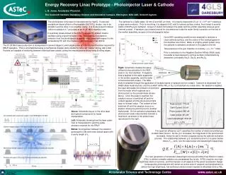
High Current Energy Recovery Linac at BNL D. Kayran, I. Ben-Zvi, D.S. Barton, D. Beavis, M. Blaskiewicz, J.M. Brennan A. Burrill, R. Calaga, P. Cameron,X. Chang, R. Connolly, D.M. Gassner, H. Hahn, A. Hershcovitch, H.-C.Hseuh, P. Johnson, J. Kewisch, R. Lambiase, V.N. Litvinenko, W. Meng, G. McIntyre, T.C. Nehring, A. Nicoletti, D. Pate, J. Rank, T. Roser, T. Russo, J. Scaduto, K.S.Smith, T. Srinivasan-Rao, N.W. Williams, K.-C. Wu, V. Yakimenko, K. Yip, A. Zaltsman, Y. Zhao, Brookhaven National Laboratory, Upton, NY, USA H.P. Bluem, A. Burger, M. Cole, A. Favale, D. Holmes, J. Rathke, T. Schultheiss, A. Todd, Advanced Energy Systems, Medford, NY, USA J. Delayen, W. Funk, L. Phillips, J. Preble, Thomas Jefferson National Accelerator Facility, Newport News, VA, USA
Outline • ERL prototype • Goals & Parameters • Step by Step tests • SRF gun, SRF cavity, beam dump • Future steps: • return loop for ERL - single and double turns • beam stability and feedbacks tests • ERL modes of operation • CW and test modes for Navy and DoE • Test relevant for the eRHIC concept • Conclusion
ions Brahms RHIC II Phobos Gun Compressor ions electrons Linac 1 Linac 2 Phenix Electron cooling Linac 3 electrons Star Beam dump ions Linac 4 Stretcher EBIS Booster Linac AGS Electron cooler forRHIC IIproject http://www.agsrhichome.bnl.gov/eCool/
Goals for ERL R&D program at BNL • Test the key components of the RHIC II electron cooler: • Au-Au luminosity 7x1027 cm-2sec-1, 10- fold boost in p-p luminosity • Test the key components of the High Current Energy Recovery Linac based solely on SRF technology • 703.75 MHz SRF gun test with 500 mA • high current 5-cell SRF linac test with HOM absorbers • Single turn - 500 mA • Two turns - 1 A….. • test the beam current stability criteria for CW beam currents ~ 1 A • Test the key components for future linac-ring e-p and e-ion collider eRHIC with luminosity of 1034 cm-2sec-1 per nucleon • 10-25 GeV SRF ERL for eRHIC • SRF ERL based an FEL -driver for high current polarized electron gun • Test the attainable ranges of electron beam parameters in SRF ERL
30-35 MeV e- 15-20 MeV Laser Cryo-module Cryo-module Beam dump e- 2.5MeV SC RF Gun e- 2.5 MeV SRF cavity 1 MW 703.75 MHz Klystron 50 kW 703.75 MHz system Control room
Super Conducting RF 2.5 MeV Gun with Diamond Amplified Photocathode Initial conceptual design for a superconducting gun with high quantum efficiency cathode. Emission enhancement (x 30-80)using a diamond window
Injection into ERL Lambertson septum 20 MeV Septum-magnet 2-2.5 MeV
Standard Laser z 15-20 MeV from ERL From the SC RF Gun 2.5 MeV Separating magnet Optimized Laser Solenoid Solenoid Standard and optimized merging systems
Chicane and Zigzag merging systems Results of Parmela simulation for 1 nC e-bunch from the cathode to the end of the linac: black dashed curve is for a round beam passing without bends; blue curves are for a compensated chicane, red curves are for Zigzag merging system. In contrast with where horizontal emittance suffers some traditional chicane growth as result of the bending trajectory, the Z-system(zigzag) the emittances are equal to each other and are very close to that attainable for the straight pass.
The emittance and the dispersion compensation: (Parmela simulation) Charge: 1.4 nC/bunch Emittances at Linac enrtance: ex ~ 1.7 mm, ey ~ 1.5 mm Emittances and beam sizes as a function of path length.
HOM ferrite assembly Space frame support structure Tuner location 2K main line 4” RF shielded gate valve Cavity assembly Vacuum vessel Vacuum vessel 2K fill line Outer magnetic shield He vessel Thermal shield Fundamental Power Coupler assembly Inner magnetic shield Super Conducting 5-cell 703.75 MHz RF linac with HOM damping
3.7 m 11.2 m ERL Lattice is very flexible Lattice of ERL has bilateral symmetry: it comprises of six 60o dipole magnets, twenty five quadrupoles and two solenoids Lattice functions for the case of zero, positive (2 m) and negotive (-2 m) longitudinal dispersion: Figure shows - and D - functions evaluations along the loop.
Control of m12 for studying the transverse stability limits in both horizontal and vertical directions Control of longitudinal compaction factor for studying longitudinal dynamics Main features of ERL Excitation process of transverse HOM
Stability of ERL (R. Calaga) • TDBBU, MatTBBU give for ERL with this cavity stability limit: currents up to ~1.8 A (1,800 mA !) for a proper lattice • We plan to increase M12 in order to measure the TBBU and to compare with predictions by TBBU
Plans & Conclusions • The design and the construction of the R&D ERL is going according to a very aggressive plan • We plan to start commissioning of the R&D ERL in late 2006/early 2007 • The prototype ERL will demonstrate the main parameters of the e-beam required for e-cooling • The prototype will also serve as a test bed for studying issues relevant for very high current ERLs and high power FELs