Download

1 / 42
420 likes | 559 Vues
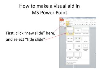
POWER-AID. GROUP 6 FALL 2011. GROUP MEMBERS: Chris Diller Arman Murat Christian Aranha Kurt Riecken. Project Description. Power Strip Modules Generator Power Monitoring Module Automatic Transfer Switch Module User Touch Screen Interface Wireless communications .

E N D
POWER-AID GROUP 6 FALL 2011 GROUP MEMBERS: Chris Diller Arman Murat Christian Aranha Kurt Riecken
Project Description • Power Strip Modules • Generator Power Monitoring Module • Automatic Transfer Switch Module • User Touch Screen Interface • Wireless communications Power-Aid is a home power monitoring system that allows a homeowner to keep track of appliance power consumption as well as monitoring and regulating emergency power in times of utility power loss. Our Design Content: Provide by Homeowner: • Home Generator (any size) • Automatic Transfer Switch
Motivation • Loss of power during natural disasters • Hassle of flipping circuit breakers on/off • Safeguarding of expensive home generator • Ease of use for the inexperienced user • Gives homeowner insight to individual appliance power consumption and how to conserve energy usage.
Goal and Objectives • Design a user-friendly touch screen interface for the user to interact with the system. • Design compact power strip modules to appeal to the aesthetics of the users home. • Design the power strip modules for easy expansion to current system. • Make the home owner aware of energy consumption and conservation
Specifications • Measure current up to 15A (standard home circuit breaker size). • Measure up to 120V (+/- 5 volts for utility fluctuations). • Calculate power consumption with +/- 5% error. • Ability to add up to 20 power strip modules to the system. • Software will automatically warn the user when the generator is outputting 90% of its total power capacity. • Wireless communication range of modules shall be at least 100 feet from touchscreen controller to accommodate average size house. • ADC that is at least 10 bits wide for 1024 steps of resolution in power calculations. • Send data every 5 seconds and enter sleep mode in between transmissions.
System Block Diagram TOUCH SCREEN ATS POWER STRIP MODULE GENERATOR DISPLAY POWER MEASUREMENT ATS CONTROL POWER MEASUREMENT RELAY MAIN PROCESSOR MICRO- CONTROLLER MICRO- CONTROLLER MICRO- CONTROLLER WIRELESS RADIO WIRELESS RADIO WIRELESS RADIO WIRELESS RADIO
Generator Module Block Diagram • Contents of Generator Module • (2) Current Transformers • (2) Potential Transformers • MSP430AFE253 • TI CC2500 RF Transceiver
Power Strip Module Block Diagram • Contents of Power Strip • Solid State Relay • Current Transformer • Potential Transformer • MSP430AFE253 • TI CC2500 RF Transceiver • 15A duplex receptacle
Qscreen Controller QSCREEN CONTROLLER • Programmable in C or Forth languages. • GUI development software for easy implementation of touch screen display interface. • 4.8” diagonal viewing area. • Flash – 354KB • RAM – 509KB • EEPROM – 320B • 8 Channel 8-bit A/D at up to 100 Kbps, 0-5 V input • Expandable memory capabilities if on board memory is not sufficient. • Only external part needed is wireless communications.
Touch Screen Block Diagram • Qscreen Embedded Controller needs a wireless interface to communicate with the rest of the system. • TI CC2500 RF Transceiver will be utilized using Zigbee communication protocol. • We chose TI wireless because of the compatibility with the MSP430 and also the simplicity of the Zigbeeprotocol compared to other wireless options.
Software Flowchart Qscreen Receive Measurement Store Data In Memory Calculations/ Update Screen Yes Execute Routine No Move To Next Module Check for Touch Screen Interrupts
POWER MEASUREMENT • Power companies charge for the real power consumption. • Real power, is the cosine of Apparent Power ( P = V * I * cosƟ ) • In order to measure power we needed to build a circuit which would accurately measure the three unknowns of the power equation V, I and Ɵ.
Different Current Measuring Alternatives • Current Shunt It’s a resistive component so it consumes a lot of power itself, heats up and it is too big. • Eddy Current Sensor Magnetic fields from other components would effect the accuracy of the measurement since this sensor does its measurements from distance. It is mostly used for other measurements rather than current • Magnetic Current Sensor It seemed to be a good option but it was more complicated to work with and there was a temperature drift problem . • Current Transformer It was too big for our circuit design and is usually good for higher current measurements than 15A.
Current Sensing Circuit Honeywell CSLA2CD HECS SUPPLY VOLTAGE MIN – 5.4V TYP – 8V MAX – 13.2V SUPPLY CURRENT TYP – 13mA MAX – 20mA • Hall Effect current sensors are insensitive to dust, vibration, humidity, cold and hot so their characteristics and measuring sensitivity remain the same thanks to their very well sealed, closed structure. • They don’t get hot because of their inductive structure but not resistive. • Because of their non-mechanical structure they don’t break easily. • High speed and repeatability. • They are logic capable
How Hall Effect Current sensor Works MEASURED CURRENT = [VOUT - 4.0] / 0.033
Power Measuring Circuit • For the Power Measuring Circuit all we needed was a voltage divider in order to drop 120 Vrms to 4 VAC so MSP 430 can actually get a sine-wave read
Phase Angle • After collecting measurement from current and voltage measuring circuits, MSP 430 will calculate the phase angle by evaluating the “0” crossings of these two separate sine waves.
Solid State Relay Sharp S102S11 Solid State Relay We preferred solid state relays against mechanical Because they are smaller, more durable, create less noise, PCB compatible. Overall they are newer and a better technology. • INPUT – Low Voltage DC (Switching Relay On) • MIN – 16mA • MAX – 24mA • OUTPUT – High Voltage AC • Load Voltage Min – 80VAC • Load Voltage Max – 125 VAC • Load Current Min – 0.1A • Load Current Max – 16A
CC2500 Wireless Transceiver • CC2500 2.4 GHz, ISM band multi-channel low power transceiver • 13.3mA consumption during operation • 400nA consumption while in sleep mode • Programmed to transfer data up to 500 kBaud • Voltages between 1.8 and 3.6 volts • On chip antenna • Controlled via SPI interface • SimpliciTI
Data Out CC2500 CC2500 Awake Control Data Out Data Out Control Control Awake Awake LOCAL MSP430 Power Strip MAIN MSP430 Control Data Flow
TI eZ430-RF2500 • MSP430F2274 • CC2500 • Examples • ADC10
A/D Conversion • 10 bit analog to digital converter • Set high/low reference voltages • X = 1023*(P8 - Vref- )/( Vref+ / Vref- ) • X = 1023*(5/20) • X = 255.75
Testing Procedure • Power Sensing Circuit • MSP430 • Wireless • LCD • Software • ATS • Scaled Test
Problem Solving • RMS Value during power measurement • Reset breaker multiple times • Phase angle • Software
Microprocessor Functions • Monitor: • Takes inputs from circuit in power strip module • Measures voltage, current values • Calculator: • Power • Energy (Reactive, active, apparent) • RMS values • Transceiver: • Send calculated circuit values for each outlet • Receive commands from LCD to turn outlets on/off
MSP430 • Free microprocessor from TI • Low power • AFE series of MCUs • Built specifically for utility metering • Sample projects, code, and library of functions available on TI’s website • Built-in functions for helping to calculate voltage, current, power, as well as arithmetic operations
MSP430AFE253 Specifications • Low power consumption • One active mode: 220 µA at 1 MHz, 2.2V • Five standby modes: 0.5 µA • Supply Voltage, Vcc: 1.8V to 3.6V • Wakeup from LPMs in < 1µs • 16-bit RISC architecture • Two digital I/O ports, with 13 total programmable lines • Three 24-bit Analog-to-digital converters • Size: 7.7 x 6.2 x 1.2 mm
Code Composer Studio (CCSv4) • Alternative to IAR Embedded Workbench • Free program from Texas Instruments • Programs in C/C++ • Challenges: • Re-learning C programming (All EE in group) • Understanding MSP430 instruction syntax
MSP430 Launchpad Compatible with CCSv4 and IAR embedded workbench Comes with MSP430G2231 Most coding same as MSP430AFE Immediately available environment to test and debug code 2kB Flash USI (I2C, SPI) 8-channel ADC Tutorials on wiki site TI Third parties Cost: $4.30 (or free)
Future Improvements • We wished to add more programming aspects into the project but we didn’t have a programmer in our group. If we ever have time we would like to get an Android application added to the project. Since as a part of the project we can turn an outlet on and off, we thought it would be nice to turn the AC or the water heater on and off from our cell phones. This way power consumption would be reduced drastically since they can only be on 20 minutes before the user arrives home.