Download
1 / 39
400 likes | 542 Vues
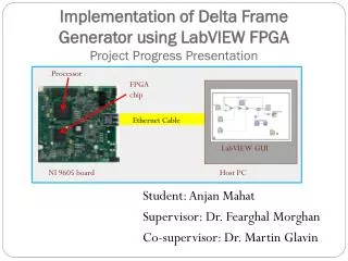
FPGA implementation of trapeziodal filters final presentation. Instructor: Evgeniy Kuksin Preformed by: Ziv Landesberg Duration: 1 semester . Project goal from presentation.

E N D
FPGA implementation of trapeziodal filtersfinal presentation Instructor: EvgeniyKuksin Preformed by: ZivLandesberg Duration: 1 semester
Project goal from presentation • Create a FIR filter that can process pulses from photon counting detectors and perform Peak Detection using NI Labview FPGA.
Progress so far • The project is completed! • Final clock rate – 125MHz (due A/D) • Successfully processing 4 channel simultaneously
System description Photons FPGA - Readout To PC Peak Detector Shaper ADC +
Project Block Diagram • A\D • NI 5761 • 14 bit • 125 MHz FPGA(125MHz) • Signal generator • (Preamplifier emulator)
Reasons to use Trapezoidal shaper over other shapers • Trapezoidal can achieve optimal noise performance from signal. Trapezoidal Shaper, unlike many analog pulse shaper, immune to “ballistic deficit”, that causes energy distortion in the spectrum. • Trapezoidal shaper can not be implemented by analog circuits.
Coefficients calculation • The Coefficients were calculated by the method at the article of “On nuclear spectrometry pulses digital shaping and processing” , the biexponential pulse part. the method is to inverse the transfer function of the pulse(making it a digital delta) , and then convolute the delta with a trapezoid. Due to the fact that both the inverse function of the pulse and the trapezoid were finite length , the resulted filter was FIR.
Coefficients calculation code Calctrapez impulse response Delete zeroes from output Calc invers function of pulse
The signal generation • The input signal was generated at 2 main stages : • 1) create an array with Poisson distributed digital delta’s in it. It was done by the Poisson noise generator, that each event was transformed to delta, and each none event was transformed to zero. • 2 ) transfer the deltas to linear rising- exponential decaying pulse, was done simply by convoluting the array with the response of such pulse(with cut-off values lower than exp(-10 ))
Signal generation code Convolut deltas with wanted shape Shape of a pulse Impulse generating
Relevant graphs to previous slide Impulses Wanted shape Resulted signal
The method of building the filter The building of the filter in Labview was done using the fir template already existing in the program. So first stage was to create a fds file to generate filter from it. The second stage was to use the automatic filter generation
Device resources Distributed arithmetic does not use DSP units !
Sucessful results at 150MHz(no noise) Input signal Shaped signal
Successful result with noise Input signal Shaped signal Result of shaper with ballistic defflict histogram
Final graph result(8 length, 1 rise time) Current Next shper (8 rise time) 6 rise time shaper
Sum up results of last three shapers Mean-60 Std-60 Mean-120 Std-120 Std-140 Mean-140
Sum up multi-channel results mean std
conclusion • The shaper which is most resistance to noise is the 16 length, with 8(sample) rise time. But apparently he is effected by quantization effect, and he caused distortion in pulses heights( probably because they have different rise time) • The 8 length shaper is nearly unaffected by quantization effect, and is the not distortive . The third filter is kind of the middle between them, with low noise and low distortion.
Conclusion(improvements) • The final system is operating at 125MHz due to the clock rate of the A/D(can only be 125MHz or 250MHz). However the “bottle neck” of the system is the FIFO to the host, so in order to increase throughput we could create the histogram of the peak detector on the FPGA himself, and send it to the host(needs slower FIFO to do it).