Download
1 / 20
200 likes | 395 Vues
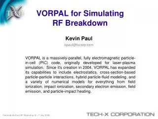
Multipactor Simulations with VORPAL. C. J. Lingwood, G. Burt, A. C. Dexter, Lancaster University, J . D. A. Smith, P.H. Stoltz, Tech-X P . Goudket , STFC Daresbury Laboratory. What is multipactor. Self sustaining resonant free electron avalanche phenomenon.

E N D
Multipactor Simulations with VORPAL C. J. Lingwood, G. Burt, A. C. Dexter, Lancaster University, J. D. A. Smith, P.H. Stoltz, Tech-X P. Goudket, STFC DaresburyLaboratory
What is multipactor • Self sustaining resonant free electron avalanche phenomenon. • Electrons impacting a surface cause secondary electrons to leave it which strike the same (or another) surface ….. • Amplification caused the probability of multiple secondary electrons • Normally investigated in terms of onset • The level of saturation is of interest when multipactor cannot be avoided or supressed • Power into components
Multipactor • Stability caused by electron trajectories resonant with the RF • Amplification caused the probability of multiple secondary electrons • Normally investigated in terms of onset • The level of saturation is of interest when multipactor cannot be avoided or supressed • Power into components
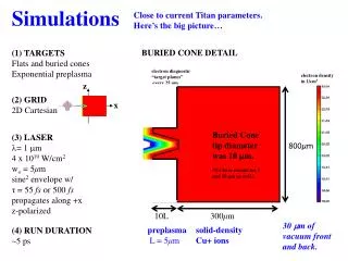
What does the simulation look like? • Results presented from a transverse 2D slice (looking down the waveguide in the direction of propagation) • Ease of interpretation of results and computational efficiency • Assumes drift in z is small • Assumes change in field in z is sufficiency small • 3D simulations do agree • 400kW peak power level • Furman-Pivi secondary emission model used 0.433m y TE10 @ 500MHz Stainless steel z 780 cells 0.102m x
2D? I thought this was HPC? • FDTD requires a lot of communication between nodes • lancs2 uses gigabit network connections • Above 4 nodes (32 cores) it got slower • 3D just too slow
Particle Implementation • Two ways to represent the particles • Variable weight macro particles • Fewer particles • They won’t stick around (end up with one MASSIVE particle) • Lower resolution
Particle Implementation • Fixed weight macro particles • More particles (harder) • Stable • Macro particles containing 10^7 electrons • 10^7-10^10 particles
How to get the trajectories • Can’t uniquely name fixed weight particles when using secondary emission. • Have a secondary population with weight 1as tracer particles. • Unfortunately no trajectory statistics
What changes with space charge? • The electrons perturb the electric field to such an extent that electrons aren’t accelerated away from the surface • Space charge at surface shieldselectrons from accelerating field
Maybe there’s another way to look at this? • The bunching is is much clearer if you plot the velocity in y against y position.
How the Populations Merge • Only the high emission energy electrons can make it away from the surface • Reflected • Rediffused • Some electrons can be turned round causing the merging of the populations
True Secondary Electrons • Emitted at all phases at 1-10eV • None make to the other side • Single loop trajectory
True Secondary Electrons • High impact energy from low emission energy (80 times!) • Or ~0eV impact energy • 2 is a resonant flight phase • Energies below 8eV are not resonant and contribute to the cloud
Power Dependence of Saturation Current • The multipactor peaks then trails off as the SEY drops • No bands! Mean impact current (A)
Experimental Comparison • Experimental data is differentiated faraday cup data. • Both nearly “featureless”
Conclusions • Very very time consuming on a single pc • Pretty quick on even an unsuitable cluster • Not all clusters are created equal • Data analysis is more time consuming than the simulation