Download
1 / 16
220 likes | 805 Vues
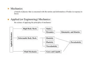
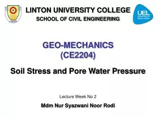
LINTON UNIVERSITY COLLEGE SCHOOL OF CIVIL ENGINEERING. GEO-MECHANICS (CE2204). Stresses Under Applied Load. Lecture Week No 4 Mdm Nur Syazwani Noor Rodi. INTRODUCTION. The distribution of stress depends on: Stiffness of foundation Compressibility or stiffness of soil

E N D
LINTON UNIVERSITY COLLEGE SCHOOL OF CIVIL ENGINEERING GEO-MECHANICS(CE2204) Stresses Under Applied Load Lecture Week No 4 MdmNurSyazwani Noor Rodi
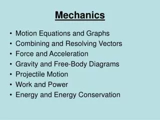
INTRODUCTION • The distribution of stress depends on: • Stiffness of foundation • Compressibility or stiffness of soil • Loading conditions – uniform or point.
STIFFNESS OF FOUNDATION Contact pressures beneath foundations under uniform loading
DETERMINATION OF SOIL STRESSES DUE TO APPLIED LAODS In civil engineering, increases in vertical stresses are usually considered and Boussinesq in 1885 developed expressions for various loading conditions, based on the following soil conditions: • Semi-infinite in both lateral and vertical directions • Isotropic (same in all directions) • Homogeneous (uniform, i.e. not layered) • Elastic (Hooke’s law of stress and strain)
BOUSSINESQ EQUATION (1885) Where Ip = the point load influence factor Applicable only for point loads, Q
EXAMPLE 1 • A foundation carrying a point load of 500kN will be place on the site at ground level. Determine the variation of Δσ vertically to the depth of 10m for the following: • 1m offset from the point load • 3m offset from the point load • 5m offset from the point load
FADUM’S CHART (1948) • Only applicable to: • Rectangles structure • Increase beneath a corner of the foundation
EXAMPLE 1 Figure below show the plan of a rectangular foundation which transmit a uniform contact pressure of 180kPa. Determine the vertical stress induced by this loading at a depth of 3m, 5m &10m below point A, B, C & D 4m 20m 2m 6m 10m 12m 3m 2m A B C D
NEWMARK’S CHART (1942) N = Number of segment Iq = Influence value/factor q = Vertical stress Applicable to any shaped foundation
EXAMPLE 1 • Consider a circularly loaded area on the ground surface. Given diameter of circular area of 1500mm and uniform pressure of 200 kN/m2, Determined the vertical stress induced by this loading at • a depth of 3m below the centre of the foundation • a depth of 5m below the circumference of the foundation • a depth of 3m below the point of 4.5m offset from the centre of the foundation
TUTORIAL 1 Figure below shows the plan of a large circular raft foundation (d = 20m); the centre area (d = 10m) transmits a contact pressure of 60kPa and the outer annular area transmits a contact pressure of 150 kPa. Using the Newmark’s chart provided, calculate the intensity of vertical stress induced at point in the soil mass 6m below A, B and C. A B C