Download
1 / 3
30 likes | 195 Vues
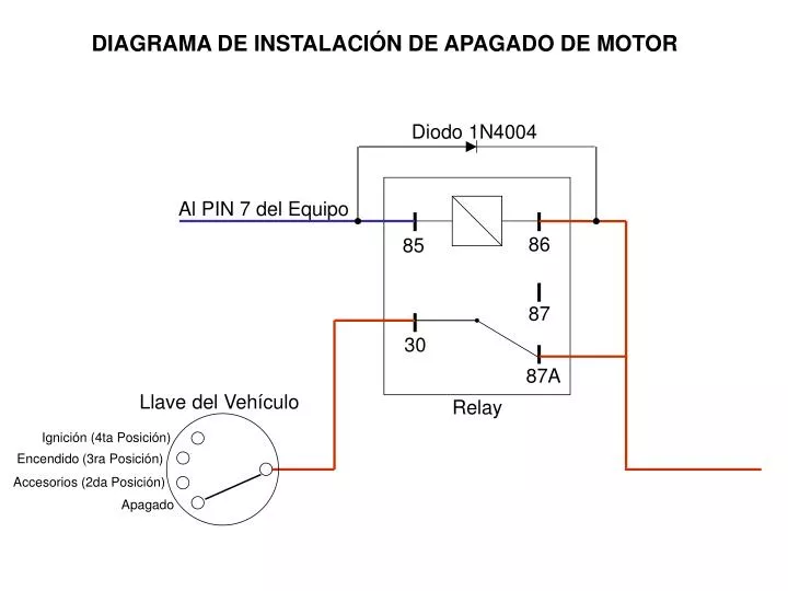
DIAGRAMA DE INSTALACIÓN DE APAGADO DE MOTOR. Diodo 1N4004. Al PIN 7 del Equipo. 86. 85. 87. 30. 87A. Llave del Vehículo. Relay. Ignición (4ta Posición). Encendido (3ra Posición). Accesorios (2da Posición). Apagado. DIAGRAMA DE INSTALACIÓN DE CORTE DE IGNICION. Diodo 1N4004.

E N D
DIAGRAMA DE INSTALACIÓN DE APAGADO DE MOTOR Diodo 1N4004 Al PIN 7 del Equipo 86 85 87 30 87A Llave del Vehículo Relay Ignición (4ta Posición) Encendido (3ra Posición) Accesorios (2da Posición) Apagado
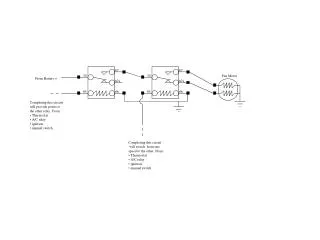
DIAGRAMA DE INSTALACIÓN DE CORTE DE IGNICION Diodo 1N4004 Al PIN 7 del Equipo 86 85 87 30 87A El cable, cuando seenciende el vehículoNO pierde voltaje Relay Llave del Vehículo Ignición (4ta Posición) Encendido (3ra Posición) Accesorios (2da Posición) Apagado
DIAGRAMA DE INSTALACIÓN DEL CABLE EN EL EQUIPO SKYPATROL Arnés de Conexión 1 2 3 4 5 6 EQUIPO Paro de Motor o Corte de Ignición 7 Sensor de Ignición 8 Botón de Pánico 9 Ignición de Equipo (Blanco) 10 Corriente 12 Volts 11 Tierra 12