Download
1 / 40
420 likes | 614 Vues
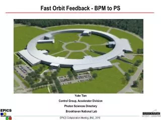
Fast Orbit Feedback System for NSLS-II. Kiman Ha NSLS-II Controls Group EPICS Collaboration meeting Oct 22~26, 2012. Outline. About NSLS-II Technical Requirement and cell structure Fast Orbit Feedback overview Hardware for FOFB Beam Position Monitor (BPM)

E N D
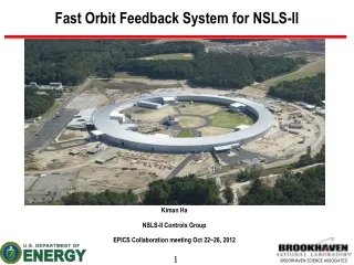
Fast Orbit Feedback System for NSLS-II Kiman Ha NSLS-II Controls Group EPICS Collaboration meeting Oct 22~26, 2012
Outline About NSLS-II Technical Requirement and cell structure Fast Orbit Feedback overview Hardware for FOFB Beam Position Monitor (BPM) Corrector Power Supply Controller Cell Controller (CC) Timing synchronization FOFB System Feedback Algorithm Feedback Implementation EPICS IOC configuration Status and Plan Summary
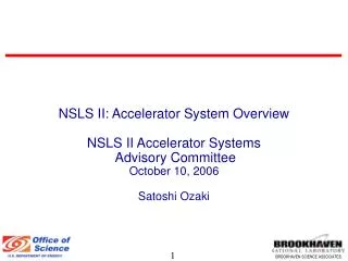
About NSLS-II (http://www.bnl.gov/ps/nsls2/about-NSLS-II.asp ) Purpose To provide extremely bright x-rays for basic and applied research in biology and medicine, materials, chemical sciences, geosciences, environmental sciences, and nanoscience Sponsor U.S. Department of Energy (DOE), Office of Science, Office of Basic Energy Sciences Costs $912 million to design and build Features State-of-the-art, medium-energy (3 GeV) electron storage ring that produces x-rays up to 10,000 times brighter than the NSLS Users Researchers from around the world
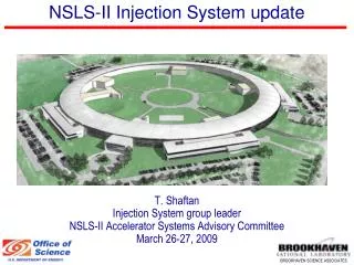
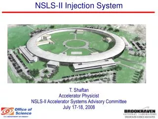
Technical Requirement & Specifications SR Injection System
BNL site field vibration measurement Displacement PSDs at locations near the NSLS-II site (Source: N. Simos) RMS Displacements at CFN ( 0.5-4) Hz : 200 nm (4-50) Hz : 20 nm (50-100) Hz : 0.4 nm NSLS-I X-ray ring (Vertical in Operations since Sept. 2002)
SR BPMs and Correctors Location 2 1 BPMs 2 3 1 3 4 6 5 SC SC FC FC SC FC SC SC • Slow correctors (Qty=6) • Slow response – 2 Hz • Strong strength – 800 μrad • Utilized for – • Alignment • Slow orbit feedback • Fast correctors (Qty=3) • Fast response – 2 kHz • Weak strength – 15 μrad • Utilized for – • Fast orbit feedback SC 100 mm slow 156 mm slow 30 mm fast (air core)
What is Fast Orbit Feedback • Global orbit correction system for sub-micron orbit stability • Beam stabilization and high brightness • Minimize the beam instability from many different noise source -Ground settlement, power switching noise, temperature, cooling water, FAN, Insertion device gap change, fill pattern, beam intensity, booster ramp .., • Based on Singular Value Decomposition (SVD) algorithm • Read beam position data every 1 kH ~ 10 kHz • Calculate new correct kick values for minimization of the RMS orbit • Update PS set values every 1 kH ~ 10 kHz • Less then 200 nm orbit stability at 0 Hz – 1 kHz
NSLS-II Fast Orbit Feedback Specifications • Powerful Virtex-6 FPGA based hardware digital signal processor • Feedback rate : 10 kHz • Bandwidth : ~2 kHz • Number of BPMs : 180 ea NSLS-II in house designed Digital BPM • Number of Correctors : 90ea 10 ~ 15 urad, 20 bit resolution, 1 ppm response • Control algorithm : SVD, Individual Eigen mode with PID control FPGA based parallel matrix calculation • Update correct set values every 10 kHz 5 Gbps fiber optics communication for BPM and CC, 100 Mbps for PS • Remote firmware upgrade (tftp client/server), 10 miniature per unit, parallel running
Topology of the FOFB network • 30 cells • 6 BPMs per sector • 3 Fast and 6 Slow H/V correctors per sector • Cell controller distribution takes 15 us • PS controller distribution takes 5 us One Cell configuration
NSLS-II Performance requirement Storage Ring - Frev = 378KHz - Frf = 499.68MHz Injection System - Frev = 1.89MHz - Bunch Spacing = 2ns - Rep Rate = 1Hz
NSLS-II BPM Digital Front End (DFE) • BNL in house designed/developed for NSLS-II project • Very flexible environment for DSP/Firmware development • Satisfied of all NSLS-II performance requirement NSLS-II RF BPM (Production Unit) NSLS-II RF BPM (Production Unit) M.Maggipinto
ADC-Raw Data Measurement SUM Fill Patten Control for SR simulation FFT
RF BPM Production - Test Phase Noise Test Port @ ADC RF BPM Burn-In: “20-units” in Thermal Test Rack RF BPM Laboratory Unit Test Setup (Bench #1) Phase Noise (Jitter) Measurement Matlab – Generate test Report (15min test time) 700fs (RMS) 500MHz MO Timing System Test Bench #2 R&S FSUP8 Stability Test ADC Histogram (Coherent Sampling) BPM(1-8): 8hr Stability (um) 0.3488 0.2082 0.1435 0.1342 0.1230 0.1248 0.1685 0.1132 1-Million Pt. FFT V.Kurt
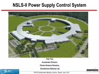
Summary Table – Storage Ring Power Supplies There is a total of 997 power supply channels used for the storage ring G. Ganetis
Power Supply Control Rack Cell Controller 100 Mbps IOC Next PS PSC 100 Mbps PSI Power Module 20bit DAC
Cell ControllerOrbit Feedback Processor • NSLS-II Orbit feedback processor is based on Xilinx Virtex6-240LX FPGA chip • We can add custom functions for FOFB design • Powerful DSP slice for parallel computing • Easily implement gigabit communication (SDI, EVR) • Integrate with embedded System (Microprocessor,DDR-3, Ethernet, UART..,) • Support model based high level design and low level logic design
FOFB Test Setup (32 Cell controller) • Successfully tested 32 Cell controller communications • BPM data used pattern generator • 5 Gbps, 32 bit custom protocol data format Ethernet to Serial Switch Linux IBM Server IOC VME EVG & FANOUT EVR Compact PCI
Cell Controller Unit IO signals (16 inputs, 12 ouptuts, 4 Vout) for fast machine protection 100 Mbit/s link for corrector setpoints I/O Migabit/s corrector setpoints 2 GB DDR3 memory DFE Virtex-6 FPGA RS232 for consol Cell Controller Embedded Event Received Gigabit Ethernet to EPICS IOC 6.5 Gigabit/s SDI link for BPM data
Digital Front End (DFE) Board • Virtex-6 FPGA • Embedded MicroBlaze soft core processor running TCP/IP lwIP stack in conjunction with EMAC Ethernet core • 2 Gbyte DDR3 SO-DIMM • 1 Gbps Ethernet • Hardware TEMAC • Memory throughput 6GBytes/sec • (6) 6.5 Gbps SFP modules • Fixed Point DSP Engine • 1Gbit FLASH memory • 4 Lemo differential output • Embedded Event Receiver • Embedded EVR compatible with MRF’s event system • Very flexible and precise timestamp and time synchronization
Timing Synchronizations • MRF’s EVG 230 – VME • MRF’s EVR-VME, cPCI, PMC • BPM – Embedded EVR • CC – Embedded EVR
FOFB timing Feedback Calculation Total processing time: 20 us To FOFB Dual Port RAM Fifo Delay Enable signal
Orbit Feedback Processor FPGA Internal CC global link BPM local link
SVD (Singular Value Decomposition)Single cell (6*3)example • SVD is most commonly used algorithm for fast and slow feedback • Already well proven algorithm during the many years * * = S • R: response matrix • (matrix containing transfer matrix elements between corrector and BPM) • M: number of BPM, N: number of corrector • U: M*N orthogonal matrix (beam position vector) • V: N*N orthogonal matrix (corrector strength vector) • ∑:diagonal matrix containing singular value of R • R-1: inverse response matrix for calculate corrector strength value
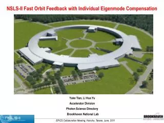
Orbit feedback system architecture • Fast orbit feedback system algorithm (MIMO system) Compensator (PID etc) Controller R-1=VΣ-1UT Accelerator R=UΣVT R: response matrix R-1: reverse response matrix FOFB baseline algorithm Offline operation: kick each corrector measure all BPM and get response matrix R calculate R-1 with SVD (10KHz) operation: measure/distribute all BPM data calculate corrector setpoints set correctors Y.Tian
Fast Orbit Feedback Algorithm – Implementation in FPGA UT Q(z) V Σ -1 Y.Tian Accelerator R=UΣVT Compensation for each eigenmode Output Decompose 180x1 Θ 1 V1 1X90 1x1 UT1 (Σ -1)1 Q1(z) 1x180 1x1 90x1 Θ 2 V2 1X90 1x1 UT2 (Σ -1)2 Q2(z) 1x180 90x1 1x1 90x1 Θ 90 V90 1x1 1X90 UT90 (Σ -1)90 Q90(z) 1x180 1x1 90x1 Use FPGA parallel computation features to implement the algorithm (assume 240 BPMs, 90 correctors) UT1, UT2… UT90: input matrix vector -- download from control system as waveform PV V1, V2 ,…V90: output matrix vector -- download from control system as waveform PV Q1(z), Q2(z), …, Q90(z): compensator for each eigenmode -- parameters download from control system
Sysgen model for single mode Y.Tian
Firmware Development • Xilinx Embedded System Tool • Model based digital signal processing design • HDL&C/C++ Mixed design • PlaneAhead for system integrations ISE Verilog/VHDL FPGA Microblaze Matlab System Generator Plan Ahead Elf, bitfile
FPGA partition for hardware timing optimization Virtex-6 FPGA pin location EVR Cell SDI BPM SDI Flash Controller Xilinx Planeahed is very powerful tool for development of the FPGA application
NSLS-II FOFB Status • Conceptual design complete • Matlab/Simulink simulation and FPGA implementation • Hardware production • Chassis and DFE completed (50 ea) • I/O board completed (50 ea) • BPM all unit production completed • SDI (Cell node, BPM node) 5 Gbps communication test completed • SDI for Power Supply 100 Mbps Control communication test completed • Machine Protection is not yet implemented (Collection requirement..) • BPM SDI integration test Completed • Feedback algorithm simulation completed • Last week started FOFB main project integrations
Development Schedule • Integrate Feedback processing module in the main project (~Dec/2012) • BPM side SDI integration (Oct, Nov/2012) • We tested pattern data for communication and we need test with real BPM data • BPM and Cell controller communication test (~Nov/2012) • EPICS IOC integration (~ Jan/2013) • High level and Diagnostic software design (~2014) • Commissioning of the Storage Ring (4/26/2012 ~ 9/13/2013) • FOFB system will be install 2/1/2013 ~
Summary -Digital BPM system 33% (100) ready for Install and commissioning -All Cell controller is ready for test and installation -We implemented simple and Roberts protocol for global BPM data distribution -We tested 32 remote cell communication link and BPM local link communication Both worked well -Ready FOFB algorithm integration in to FPGA (Last week) -We assume there are many technical issues for commissioning and operation - BPM/PS performance, FOFB Algorithm, Communication, Diagnostics But we have a lot of experience to solve that any problems
Acknowledgement • BPM/ Cell controller development : • Kurt Vetter (Diagnose Group) • Joseph Mead (Instrumentation Group) • Alfred Dellapenna (Diagnose Group) • Marshall Maggipinto (Diagnose Group) • Joseph De Long (Controls Group) • Yuke Tian (Controls Group) • Yong Hu (Controls Group) • Om Singh (Diagnose Group) • Bob Dalesio (Controls Group) • PSC and PS design: • Wing Louie (Power Supply Group) • John Ricciardelli (Power Supply Group) • George Ganetis (Power Supply Group)
Linac/LTB LtB (3) RF BPM LINAC (5) RF BPM BPM IOC (IBM server) LtB (3), and LINAC (5) RF BPM Thermal Rack Installation M.Maggipinto
Single bunch Measurement 1st measured beam with RF BPM (LINAC BPM #1). 120pC Single-Bunch “April 2, 2012”