Download

1 / 28
430 likes | 2.26k Vues
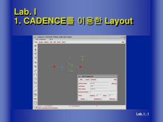
Hspice & Nanosim. 溫家聖 sheng@garfield.cse.nsysu.edu.tw. Pre-Layout Simulation. 本部份原本應該要最早做的,但若我們先利用 Schematic editor 畫好電路圖,進而直接轉出 hspice file ,就可免除人工撰寫 hspice file 的麻煩。 本部份是為了要確定電路可達到規格要求。. pre-layout simulation. Hspice. Schematic View. CDL out. Inv.net. 修改 netlist 檔.

E N D
Hspice & Nanosim 溫家聖 sheng@garfield.cse.nsysu.edu.tw
Pre-Layout Simulation • 本部份原本應該要最早做的,但若我們先利用Schematic editor畫好電路圖,進而直接轉出hspice file,就可免除人工撰寫hspice file的麻煩。 • 本部份是為了要確定電路可達到規格要求。 pre-layout simulation Hspice
修改netlist 檔 移掉subckt與pin腳宣告,加上PULSE波形輸入與測量Delay或Power指令
HSPICE circuit simulation Mn1 15 17 20 20 NMOS W=5U L=0.5U <AD=…> Mp1 15 17 12 12 PMOS W=10U L=0.5U <AD=…> Rgnd 20 0 1K Cload 15 0 100F .MODEL NFET NMOS <parameters> (from technology files) .MODEL PFET PMOS <parameters> (from tech. files) Vin 17 0 PULSE(V1 V2 TD TR TF PW PER) .DC Vin 0 VDD VSTEP .TRAN TSTEP TSTOP
tf tr tpHL tpLH 傳輸延遲 (Propagation Delay)和上升下降時間 Vin Vout (V) t (sec) x 10-10 TpHL:從Vi 變化的50 % 到達Vo 變化(Vo 由High 至Low ) 的50 %之間所經過的時間。 TpLH:從Vi 變化的50 % 到達Vo 變化(Vo 由Low 至High)的50 %之間所經過的時間。 Tp:一般而言,TpHL 不會等於TpLH,因此我們定義Tp 為平均延遲時間,亦即: Rise time 指上升時間,output 由10 % 至90 % VDD Fall time 指下降時間,output 由90 % 至10 % VDD
Delay example---TSMC 18um • ************************************************************************ • * auCdl Netlist: • * Library Name: tsmc0352p4m_wen • * Top Cell Name: inv • * View Name: schematic • * Netlisted on: Oct 13 11:32:02 2006 • ************************************************************************ • .PARAM • *!代表全域變數 • .GLOBAL gnd! vdd! • *The first two examples specify a DC voltage source of 1.8 V connected between node 1 and ground. • *給予電壓源1V • *v0 vdd! gnd! 1.8 • v0 vdd! 0 dc 1.8 • v1 I 0 pulse 0 1.8 2ns 10ps 10ps 10ns 20ns • *M開頭為MOS 接下來是 Source gate drain 接下來為SPICE model name1, MOS W width, L width 最後則是接並聯的個數. • MM1 ZN I gnd! gnd! nch W=500.0n L=0.18u m=1 • MM0 ZN I vdd! vdd! pch W=500.0n L=0.18u m=1 • c0 out gnd! 0.1p • .tran 0.1ns 40ns start=0. *暫態分析 取樣0.1ns 從0ns到40ns • .temp 25 *溫度設定為25度C • *測量Delay • *The format specifies substatements TRIG and TARG. These two statements specify the beginning and ending of a voltage or current amplitude measurement. • *The rise, fall, and delay measurement mode computes the time, voltage, or frequency between a trigger value and a target value. • .meas tran trfd trig v(I) val=0.9 rise=2 targ v(ZN) val=0.9 fall=2 • *上升下降時間是測量上升或下降的10%到90%所需花的時間 • .meas tran trise trig v(ZN) val=0.18 rise=2 targ v(ZN) val=1.62 rise=2 • .meas tran tfall trig v(ZN) val=1.62 fall=2 targ v(ZN) val=0.18 fall=2 • .op *將spice跑的每個MOS資訊秀出,包括gate端電容 • .save • .option post *產生讓scope讀的資料 • .lib ‘rf018.l’ TT *設定製程偏移 • .end
製程偏移( process variation ) • 以UMC 90n而言,為nMOS and pMOS的速度而言皆有三種可能 Fast (F), Slow (S),typical (T), 所以如下圖所示有五種組合:TT (nMOS and pMOS is Typical), FF (nMOS and pMOS is Fast), FNSP (Fast nMOS and Slow pMOS), SNFP (Slow nMOS and Fast pMOS), SS (nMOS and pMOS is slow).
scpoe 在提示符號下打scope &的指令即可開啟波形
量測 Dynamic Power • monte carlo method • 改變例子中的暫態分析如下所示: • .tran 0.1ns 180ns start=0. sweep monte=100 • *暫態分析 取樣0.1ns 從0ns到180ns 跑的次數為100次
量測 Dynamic Power • 在spice file中加入下列參數: • .PARAM • +z11=limit(0.9,0.9) *設定它以0.9為中心,加或減0.9所以它會是0或1.8v • +z12=limit(0.9,0.9) • .MEAS TRAN AVERAGE_POWER AVG POWER *設定量測平均功率 • .MEAS TRAN MIN_POWER MIN POWER *設定量測最小功率 • .MEAS TRAN MAX_POWER MAX POWER *設定量測最大功率 • 將輸入訊號改為 • pulse z11 z12 0ns 0ps 0ps 30ns 60ns *將電壓源改變成參數讓他變動
量測 static Power • 在語法中下了.OP • 在執行完Hspice 之後會在執行結果中發現voltage information 如下所示,其power 便為static power. • static power 為3.2496nW
取得input pin 電容 • 在xxx.SP檔中加入 .op Gate端電容,兩者相加
Nanosim • Nanosim 它可以直接跑大部分Hspice的語法 • How to execute? • > nanosim –nspice CMOS_inv.sp –o inv –out fsdb • 其結果會產生在指定的 inv.meas中, 執行nWave來觀查波形, 只是files of type 選擇FSDB(*.fsdb)
Example-nanosim • ***nanosim*** • .lib 'rf018.l' TT • .GLOBAL VDD! • V0 VDD! 0 DC 1.8 • M2 OUT I VDD! VDD! pch L=0.18u W=1u • M1 OUT I 0 0 nch L=0.18u W=0.5u • V1 I 0 pulse 0 1.2 0 0 0 10n 20n • .TRAN 0.1n 50n START= 0. • .meas tran tdr trig v(I) val=0.9 fall=2 targ v(OUT) val=0.9 rise=2 • .meas tran tdf trig v(I) val=0.9 rise=2 targ v(OUT) val=0.9 fall=2 • .meas tran tdrise trig v(OUT) val=0.18 rise=2 targ v(OUT) val=1.62 rise=2 • .meas tran tdfall trig v(OUT) val=1.62 fall=2 targ v(OUT) val=0.18 fall=2 • .TEMP 25.0000 • .option post • .END
Power measure • Nanosim 有特別針對power measure 作出其configuration command如下例所示,存在*.cfg檔中 • Set_sim_moslevel 2 • report_block_powr inv track_power=1 split_wasted=1 • * report_block_powr 是將power information show出來的command 後面接的參數依序為top cell name, 動態power 設定, 靜態power設定. • 我們下了上述的command 在inv.cfg中, 便執行下列指令: • > nanosim –nspice CMOS_inv.sp –o inv –c inv.cfg –out fsdb
Result dynamic power:它會依照你的工作頻率不同而有所不同,因此我們一般會除上你的工作頻率,再表示成W/MHz. static power=leakage power + short power leakage power short power