Download
1 / 77
790 likes | 1.03k Vues
Critical Power Distribution Systems. IEEE Presentation May 2005 Mike Filley. Tonight’s Points of Discussion. What is a Critical Power Distribution System? NEC Considerations “Classical” Distribution Systems

E N D
Critical Power Distribution Systems IEEE Presentation May 2005 Mike Filley
Tonight’s Points of Discussion • What is a Critical Power Distribution System? • NEC Considerations • “Classical” Distribution Systems • Addition of Energy Storage and Power Generation creates a Critical Power Distribution System • Some Representative Systems • Reliability Principles • Reliability versus Availability • What does it mean anyway? • The importance of proper commissioning • Single-point-of-failure analysis • The system must be maintainable • Reliability vs. Safety • Energy Storage Systems • Grounding Considerations • Achieving Better Selectivity
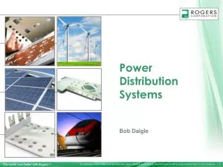
Critical Power Distribution Systems • Found in client facilities where availability of electric power must be maintained 100% of the time: industrial facilities with 365/7/24 production schedules, data centers, telecommunications facilities ... • Where unplanned (and sometimes planned) power interruptions can create severe and adverse (economic) impact • For the purposes of tonight’s discussion, those systems which typically fall under NEC Article 702-Optional Standby Systems • Typically contain multiple utility sources, electrochemical or electromechanical energy storage systems (UPS), and on-site power generation
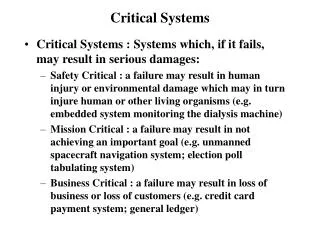
National Electrical Code Considerations • Article 700 Emergency Systems - Systems intended to supply, distribute, and control power and illumination essential for safety to human life, in the event of failure to the normal supply…fire pumps, operating room and life-support equipment, non-unit based emergency and exit lighting…or any equipment where power failure would produce serious life safety or health hazards • 10 second Availability • Segregated wiring systems • Mandatory testing and record-keeping • Ground-fault trip not required, detection recommended • If battery-provided, 1-1/2 hour supply • Multiple transfer switches for emergency, legally required standby, and optional standby circuits • Temporary or portable source required during maintenance • New requirement, selective coordination with supply side OCPD’s
NEC Considerations (cont’d) • Article 701 Legally Required Standby Systems-Systems typically installed to serve loads, such as heating and refrigeration systems, communications systems, ventilation and smoke removal, sewage disposal, lighting, and industrial processes that, when stopped due to outage of the normal supply, could create hazards or hamper rescue of fire-fighting operations • 60 second availability • Wiring may share normal system raceways • Second priority to emergency systems • Ground-fault protection not required • New requirement: selective coordination with all supply-side OCPD’s
NEC Considerations (cont’d) • Article 702 Optional Standby Systems - Systems installed to provide alternate power source for industrial and commercial buildings…to serve loads such as heating and refrigeration, data processing and communications, and industrial processes that, during a power outage, could cause discomfort, serious process interruption, damage to product or process… • Parallel operation permitted if complies with Art 705 • Portable sources permitted w/o transfer eqpt if normal source isolated and operation supervised by qualified personnel • Ground fault protection is required • Automatic operation requires disconnection from primary source • Typical protections include phase loss, sync check or synchronizing relay, reverse current or power
IEEE Standard 141 Red Book for Basic Design Considerations in a Distribution System • Safety • Reliability • System Reliability Analysis and Total Owning Cost • Simplicity of Operation • Maintenance • Flexibility
What do we need from critical power? • Never goes down • Protect equipment to minimize damage at the point of fault • Maximize worker protection • Maintainable! UTILITY A GA
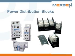
“Classical” Distribution Systems • Simple Radial • Loop and Tap-Single primary cable loop • Primary Selective-Fully redundant dual primary cables • Secondary Selective-two transformers-double ended substation-Load fed from both transformers normally, one transformer if necessary. • Primary/Secondary Selective-Dual primary cables, two transformers in double ended substation configuration. • Secondary or spot network-Transformers operated in parallel, utilizing network protectors or 67/25V/79 relays with circuit breakers.
Primary Selective - Line Selector BUS B BUS A
Secondary Selective • May be key-interlocked or Automatic Throwover System • 1. Main-Tie-Main. Two sources with both supplying load power. Loss of voltage on either source effects automatic transfer to remaining voltage source and feeds all loads. • 2. Normal-Alternate. Alternate source may be second utility source or on-site customer owned generator. All loads fed from one source. If generator is alternate source, load shedding may be necessary depending on generator capacity. • 3. Re-transfer to normal mode. What is customer tolerance for “dead bus” during re-transfer? Should re-transfer be delayed? Should closed transition be considered if both sources are utility?
The integration of energy storage and power generation equipment into these classical schemes produces critical power distribution systems
A Basic Critical Power SystemGenerator/ATS/UPS w/ Single Utility Feed
How to Generate Power? GEN A UTILITY B GEN B UTILITY A BUS B BUS A
How to Generate Power? UTILITY A GEN A GEN B UTILITY B BUS B BUS A
MV or LV Generation? GEN A GEN B
Reliability - Definition The probability that the equipment will not fail within the next hour. What is your reliability at age 20?
Reliability - Definition The probability that the the equipment will not fail within the next hour. What is your reliability at age 50?
What is your Breaker’s Reliability • Reliability when? • How do you come up with the answer? System Reliability 0 Time (Years) 50
How is it done? • IEEE Gold Book • Makes fundamental assumptions about reliability • Assumes reliability declines exponentially • Uses average data from a cross section of industry - obtained by surveys • This gives us a fixed failure rate Low voltage metal enclosed circuit breaker
MUT Availability = MUT + MDT System Availability - The More Useful Index MUT = Mean Uptime MDT = Mean Downtime System Reliability Time MUT MDT
How Useful is it? 99.999% Power Availability at Computer Racks • Translates to 5.2 minutes of outage • Is it one 5.2 minute outage? • Or 50 of 6 second outages? • How about maintenance? How does that come into the equation? • What about human factors?
UTILITY A So, How do you Make Sense out of all This? UTILITY A • Do not use reliability and availability numbers as an absolute measure • Use these for comparative analyses • Consider the maintainability factor GA
In Reality, Failure Rate is not Constant Infant Mortality Wearout Failure Rate (Failures /Year) Time What does a Bathtub have to do with Critical Power System Commissioning?
Startup Versus Commissioning • The goal of equipment startup • To bring the equipment to a point where it can be safely energized • The goal of system commissioning • To bring the equipment to a point where it would properly function, delivering the level of reliability that is stipulated in system design
27 LOADS LOADS Load Bank Testing Under Full Load Finds More than Just Loose Bolts UTILITY Tie Bus PLC
How to Commission • Test under full load • Test real-life performance under various failure modes • The goal is to make it fail • Do not relax your standards • Do not cut any corners • Trust, but verify each function • 100% physical check • 100% control system check • 100% CT polarities and ratio check • 100% active component (circuit breaker, relay, etc) check • Check normal, maintenance and failure modes
The chain saw rule 1 The hand grenade rule 1 1 Due credit is given to Mike Mosman, P.E. Single Point of Failure Analysis
Mission Critical, Present Paradigm • Utility at 99.9% availability (8 hour outage per year) • Necessitates backup generators • Maintainability • Maintainability is engineered in the design of the data center such that each piece of equipment can be shut down for maintenance without jeopardizing the critical loads • Every Power Path Backed up • No single failure jeopardizes the critical load • Consideration must be given to fault clearing • Consideration must be given to the effect of grounding method • Consideration must be given to arc flash
What about Reliability vs. Personnel Protection? • In critical power systems, there often are limited options for shutting down equipment, unless redundant paths for power have been fully designed into the system…sometimes an almost impossible task. • For reliability, we want breaker selectivity, which usually means extended trip times… • For safety and minimal equipment damage, we want breakers that trip with no delay… • How do you rationalize the two objectives?
Personnel Safety • Some options to consider to reduce arc flash hazards: • Concurrent short circuit/coordination/arc flash analyses • Barriered construction • LV Bus insulation • Zone selective interlocking on ground fault and short time protective functions • High resistance grounding • Remote operation • Remote breaker setting changes
What about Energy Storage?UPS Topologies • Double Conversion • Static UPS • Rotary M-G Sets • Line Interactive • Static Technology • Rotary Technology
The Double Conversion UPSMGE, Liebert • High Losses - 6% to 10% • Filter in the input is a problem • Batteries take a lot of space and have environmental issues • Available short circuit is low - 3 times rated current • How do you ground the output? UTILITY Output XFMR Critical Load
Double Conversion RotaryThe Motor - Generator Set • High Losses • Flywheel has high power delivery capability, but low energy storage • Available short circuit can be high (14 x rated amps) - this is a good thing • How do you ground the output? UTILITY Input Machine Output Machine Critical Load Flywheel
DC The Hybrid Rotary M-G Filter Choke Power Source System Fan Thrust Bearing Brushless Excitation Stator Motor and Generator Windings in a common Stator Rotor Common Rotor with Damper winding Exciter Vertical Arrangement for low Bearing Load Stator Start motor Electrical Load Unloaded Guide Bearing
Double Conversion RotaryPiller Uniblock A.C. INPUT RECTIFIER INVERTER _ N.O. ~ N.C. RECTIFIER AUTO.BYPASS FLYWHEEL
UTILITY UPS UTILITY Critical Load Power Conversion Equip. Which is the Most Efficient Way? Critical Load
0 V0 Vm Shunt Connected Power Conditioning UTILITY Critical Load Vm > V0 Synchronous Condenser < 0 Control Components: • Excitation • Shaft Power > 0 Synchronous Generator
0 V0 Vm ACCUSINE Shunt Connected Power Conditioning UTILITY Critical Load Vm > V0 Synchronous Converter < 0
The Line Interactive Static UPSAPC, Delta Conversion UTILITY Critical Load
The Line Interactive Static UPSActive Power, Caterpillar Output XFMR UTILITY Critical Load • Rated 250 KW, 13 seconds per module • 14” high, 32” diameter • Runs at about 7700 RPM • Parallel multiple modules High Speed Flywheel
Line Interactive Rotary UPSHiTek • No tuned harmonic filter • Losses in 4% range • Choke + synchronous machine acts as a filter. • Absorbs load harmonics and blocks utility voltage harmonics • Regulates voltage and supplies the reactive power need of the load UTILITY 49% 1% Critical Load Xd’’ = 7% Rotary UPS Output Machine