Download
1 / 57
590 likes | 726 Vues
Chapter 7 Layer 2 - Technologies. Lecture Objective (Week 8). After finishing the lecture, student should be able to: Describe the IEEE 802 standards Learn Token Ring technology (by your own) Understand FDDI architecture, cable type, & signaling technique Explain how Ethernet works

E N D
Lecture Objective (Week 8) • After finishing the lecture, student should be able to: • Describe the IEEE 802 standards • Learn Token Ring technology (by your own) • Understand FDDI architecture, cable type, & signaling technique • Explain how Ethernet works • Explain the operation of Layer 2 devices
IEEE Standard Title and Comments 802 Standards for Local and Metropolitan Area Networks 802.1 LAN and MAN Bridging and Management (including Spanning Tree Protocol) 802.2 Logical Link Control 802.3 Carrier Sense Multiple Access/ Collision Detect (CSMA/CD) Access Method 802.3u Fast Ethernet 802.3z Gigabit Ethernet 802.4 Token Passing Bus Access Method 802.5 Token Ring Access Method 802.6 Distributed Queue Dual Bus Access Method (for WANs) 802.7 Broadband Local Area Networks 802.8 Fiber-Optic Local and Metropolitan Area Networks 802.9 Integrated Services (internetworking between subnetworks) 802.10 LAN/MAN Security 802.11 Wireless LANs(1 baseband IR and 2 microwave signals in the 2.4-2.5kMHz band) 802.12 High-speed LANs (100 Mbps signals using Demand Priority Access Method) 802.14 Cable TV Access Method
Overview of Token Ring and its variants • The term Token Ring refers both to IBM's Token Ring and to IEEE's 802.5 specification.
Token Ring Frame Format • Token: • Start Delimiter: alerts each station to the arrival of a frame. • Access Control Byte: contains the priority and reservation field, and a token and monitor bit. • token bit distinguishes a token from a data/command frame • monitor bit determines whether a frame is continuously circling the ring. • End Delimiter: signals the end of the token or data/command frame.
Data/Command Frames vary in size depending on the size of the information field. Data frames carry information for upper-layer protocols; command frames contain control information and have no data for upper-layer protocols. • Frame Control Byte: indicates whether the frame contains data or control information. • In control frames, this byte specifies the type of control information. • Address Fields: that identify destination and source stations. • Data Field: length of this field is limited by the ring token that holds the time, thus defining the maximum time a station may hold the token. • Frame Check Sequence (FCS) Field : The source station fills this field with a calculated value dependent on the frame contents. The destination station recalculates the value to determine whether the frame has been damaged in transit. The frame is discarded if it has been damaged. As with the token, the end delimiter completes the data/command frame.
Token Passing • Token-passing networks move a small frame, called a token, around the network. Possession of the token grants the right to transmit data. If a node that receives a token has no information to send, it passes the token to the next end station. Each station can hold the token for a maximum period of time, depending on the specific technology that has been implemented.
Token Passing • When a token is passed to a host that has information to transmit, the host seizes the token and alters 1 bit of it. The token becomes a start-of-frame sequence. • Next, the station appends the information to transmit to the token and sends this data to the next station on the ring. There is no token on the network while the information frame is circling the ring, unless the ring supports early token releases. Other stations on the ring cannot transmit at this time. They must wait for the token to become available. Token Ring networks have no collisions. If early token release is supported, a new token can be released when the frame transmission has been completed. • The information frame circulates around the ring until it reaches the intended destination station, which copies the information for processing. The information frame continues around the ring until it reaches the sending station, where it is removed. The sending station can verify whether the frame was received and copied by the destination.
Token Passing • Token-passing networks are deterministic. • we can calculate the maximum time that will pass before any end station will be able to transmit. • ideal for applications where any delay must be predictable, and robust network operation is important. Factory automation environments are examples of predictable robust network operations. • Priority System • Token Ring frames have two fields that control priority - the priority field and the reservation field. • Only stations with a priority equal to, or higher than, the priority value contained in a token can seize that token. • Once the token has been seized and changed to an information frame, only stations with a priority value higher than that of the transmitting station can reserve the token for the next network pass. The next token generated includes the higher priority of the reserving station. Stations that raise a token's priority level must reinstate the previous priority when their transmission has been completed.
Token Ring Management Mechanisms • one station act as the active monitor which performs a variety of ring maintenance functions such as • remove continuously circulating frames from the ring. • active MSAUs (multi-station access units) can see all information in a Token Ring network, thus enabling them to check for problems, and to selectively remove stations from the ring whenever necessary. • Beaconing - detects and tries to repair network faults. • When a station detects a serious problem with the network (e.g. a cable break) it sends a beacon frame. The beacon frame defines a failure domain which includes the station that is reporting the failure, its nearest active upstream neighbor (NAUN), and everything in between. • Beaconing initiates a process called autoreconfiguration, where nodes within the failure domain automatically perform diagnostics. This is an attempt to reconfigure the network around the failed areas. Physically, MSAUs can accomplish this through electrical reconfiguration.
Token Ring Signaling • Signal encoding is a way of combining both clock and data information into a stream of signals that is sent over a medium. Manchester encoding combines data and clock into bit symbols, which are split into two halves, the polarity of the second half always being the reverse of the first half. Because both 0's and 1's result in a transition to the signal, the clock can be effectively recovered at the receiver. • Token-Ring uses the differential Manchester encoding method
Token Ring Media and Physical Topologies • IBM Token Ring network stations (often using STP and UTP as the media) are directly connected to MSAUs, and can be wired together to form one large ring. • Patch cables connect MSAUs to other MSAUs that are adjacent to it. Lobe cables connect MSAUs to stations. MSAUs include bypass relays for removing stations from the ring
Fiber Distributed Data Interface (FDDI) specifications • Media Access Control (MAC) - defines how the medium is accessed, including: • frame format • token handling • addressing • algorithm for calculating a cyclic redundancy check and error recovery mechanisms • Physical Layer Protocol (PHY) - defines data encoding/decoding procedures, including: • clocking requirements • framing • other functions
FDDI Specifications • Physical Layer Medium (PMD) - defines the characteristics of the transmission medium, including: • fiber optic link • power levels • bit error rates • optical components • connectors • Station Management (SMT) - defines the FDDI station configuration, including: • ring configuration • ring control features • station insertion and removal • initialization • fault isolation and recovery • scheduling • collection of statistics
FDDI Format • preamble - prepares each station for the upcoming frame • start delimiter - indicates the beginning of the frame, and consists of signaling patterns that differentiate it from the rest of the frame • frame control - indicates the size of the address fields, whether the frame contains asynchronous or synchronous data, and other control information
FDDI Format • destination address - contains a unicast (singular), multicast (group), or broadcast (every station) address; destination addresses are 6 bytes • source address - identifies the single station that sent the frame; source addresses are 6 bytes • data - control information, or information destined for an upper-layer protocol • frame check sequence (FCS) - filled by the source station with a calculated cyclic redundancy check (CRC), value dependent on the frame contents (as with Token Ring and Ethernet). The destination station recalculates the value to determine whether the frame may have been damaged in transit. If it has been, the frame is discarded. • end delimiter - contains non-data symbols that indicate the end of the frame • frame status - allows the source station to determine if an error occurred and if the frame was recognized and copied by a receiving station
FDDI MAC • FDDI uses a token passing strategy similar to Token Ring. • FDDI are deterministic. • FDDI's dual ring assures that not only are stations guaranteed their turn to transmit, but if one part of one ring is damaged or disabled for any reason, the second ring can be used. This makes FDDI very reliable. • FDDI supports real-time allocation of network bandwidth by defining two types of traffic - synchronous and asynchronous.
FDDI Signaling • FDDI uses an encoding scheme called 4B/5B. Every 4 bits of data are sent as a 5 bit code. • The signal sources in FDDI transceivers are LEDs or lasers.
FDDI Media • FDDI specifies a 100 Mbps, token-passing, dual-ring LAN that uses a fiber-optic transmission medium. It defines the physical layer and media access portion of the link layer, which is similar to IEEE 802.3 and IEEE 802.5 in its relationship to the OSI Model. Although it operates at faster speeds, FDDI is similar to Token Ring. The two networks share a few features, such as topology (ring) and media access technique (token-passing). A characteristic of FDDI is its use of optical fiber as a transmission medium.
FDDI Media • Optical fiber offers several advantages over traditional copper wiring, including such advantages as: • security - Fiber does not emit electrical signals that can be tapped. • reliability - Fiber is immune to electrical interference. • speed - Optical fiber has much higher throughput potential than copper cable. • FDDI defines the two specified types of fiber: single-mode (also mono-mode); and multi-mode. • Single-mode fiber allows only one mode of light to propagate through the fiber => higher bandwidth, and greater cable run distances => used for inter-building connectivity • multi-mode fiber allows multiple modes of light to propagate through the fiber => modal dispersion => slower bandwidth, and shorter cable run distances => used for intra-building connectivity • Multi-mode fiber uses LEDs as the light-generating devices, while single-mode fiber generally uses lasers.
FDDI Media • FDDI specifies the use of dual rings for physical connections. Traffic on each ring travels in opposite directions. Physically, the rings consist of two or more point-to-point connections between adjacent stations. • The primary ring is used for data transmission; the secondary ring is generally used as a back up.
FDDI Media • Class A, or dual attachment stations (DAS), attach to both rings. • SASs are attached to the primary ring through a concentrator, which provides connections for multiple SASs. The concentrator ensures that a failure, or power down, of any given SAS, does not interrupt the ring. This is particularly useful when PCs, or similar devices that frequently power on and off, connect to the ring. • Class B, or single-attachment stations (SAS), attach to one ring • DAS has two ports - designated A and B. These ports connect the station to the dual FDDI ring, therefore, each port provides a connection for both the primary and the secondary ring.
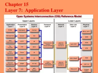
Comparing Ethernet and IEEE 802.3 • is well suited to applications where a local communication medium must carry sporadic, occasionally heavy traffic at high peak data rates. • shortly after the 1980 IEEE 802.3 specification, Digital Equipment Corporation, Intel Corporation, and Xerox Corporation jointly developed and released an Ethernet specification, Version 2.0, that was substantially compatible with IEEE 802.3. Today, the term Ethernet is often used to refer to all CSMA/CD LAN’s that generally conform to Ethernet specifications, including IEEE 802.3. • differences between Ethernet and IEEE 802.3 LANs are subtle. • Ethernet provides services corresponding to Layer 1 and Layer 2 of the OSI reference model. • IEEE 802.3 specifies the physical layer, Layer 1, and the channel-access portion of the data link layer, Layer 2, but does not define a Logical Link Control protocol. • Both Ethernet and IEEE 802.3 are implemented through hardware. Typically, the physical part of these protocols is either an interface card in a host computer or circuitry on a primary circuit board within a host computer.
100BASE-TX • 100BASE-TX (Fast Ethernet using Twisted Pair Cables) • 100BASE-FX (Fast Ethernet using Optical Fiber)
1000BASE-T • 1000BASE-T • Gigabit Ethernet over UTP
1000BASE-SX and 1000BASE-LX • 1000BASE-SX • Gigabit Ethernet over optical fiber with short-wavelength laser source • 1000BASE-LX • Gigabit Ethernet over optical fiber with long-wavelength laser source
Ethernet Frame Format • preamble - The alternating pattern of 1's and 0's tells receiving stations that a frame is Ethernet or IEEE 802.3. • start-of-frame (SOF) - The IEEE 802.3 delimiter byte ends with two consecutive 1 bits, which serve to synchronize the frame-reception portions of all stations on the LAN. SOF is explicitly specified in Ethernet. • destination and source addresses - The source address is always a unicast (single-node) address. The destination address can be unicast, multicast (group), or broadcast (all nodes). • type (Ethernet) - specifies the upper-layer protocol to receive the data after Ethernet processing is completed. • length (IEEE 802.3) - indicates the number of bytes of data that follows this field.
Ethernet Frame Format • data (Ethernet) - After physical-layer and link-layer processing is complete, the data contained in the frame is sent to an upper-layer protocol, which is identified in the type field. Although Ethernet version 2 does not specify any padding, in contrast to IEEE 802.3, Ethernet expects at least 46 bytes of data. • data (IEEE 802.3) - After physical-layer and link-layer processing is complete, the data is sent to an upper-layer protocol, which must be defined within the data portion of the frame. If data in the frame is insufficient to fill the frame to its minimum 64-byte size, padding bytes are inserted to ensure at least a 64-byte frame. • frame check sequence (FCS) - This sequence contains a 4 byte CRC value that is created by the sending device and is recalculated by the receiving device to check for damaged frames.
Ethernet MAC • Ethernet is a shared-media broadcast technology. The access method CSMA/CD used in Ethernet performs three functions: • transmitting and receiving data packets • decoding data packets and checking them for valid addresses before passing them to the upper layers of the OSI model • detecting errors within data packets or on the network • In the CSMA/CD access method, networking devices with data to transmit over the networking media work in a listen-before-transmit mode. This means when a device wants to send data, it must first check to see whether the networking media is busy. The device must check if there are any signals on the networking media.
Ethernet MAC • After the device determines the networking media is not busy, the device will begin to transmit its data. While transmitting its data in the form of signals, the device also listens. It does this to ensure no other stations are transmitting data to the networking media at the same time. After it completes transmitting its data, the device will return to listening mode. • Networking devices are able to tell when a collision has occurred because the amplitude of the signal on the networking media will increase. • When a collision occurs, each device that is transmitting will continue to transmit data for a short time. This is done to ensure that all devices see the collision.
Ethernet MAC • all devices on the network have backed off for a certain period of time (different for each device), any device can attempt to gain access to the networking media once again. • When data transmission resumes on the network, the devices that were involved in the collision do not have priority to transmit data. • Ethernet is a broadcast transmission medium. This means that all devices on a network can see all data that passes along the networking media. • not all the devices on the network will process the data. Only the device whose MAC address and IP address matches the destination MAC address and destination IP address carried by the data will copy the data.
Ethernet MAC • Once a device has verified the destination MAC and IP addresses carried by the data, it then checks the data packet for errors. If the device detects errors, the data packet is discarded. • The destination device will not notify the source device regardless of whether the packet arrived successfully or not. • Ethernet is a connectionless network architecture and is referred to as a best-effort delivery system. • Signal encoding is Manchester encoding • 10BASE-T transceivers are designed to send and receive signals over a segment that consists of 4 wires - 1 pair of wires for transmitting data, and 1 pair of wires for receiving data.
Ethernet 10BASE-T Media and Topologies • Star topology is used; communication between devices attached to the local area network is via point-to-point wiring to the central link or hub. All network traffic in a star topology passes through the hub. • The hub receives frames on a port, then copies and transmits (repeats) the frame to all of the other ports. • In Ethernet where hubs act as multiport repeaters, they are sometimes referred to as concentrators.
Ethernet 10BASE-T Media and Topologies • star topology’s advantages • is that it is considered the easiest to design and install • is its ease of maintenance since the only area of concentration is located at the hub. • is easy to modify and troubleshoot • Workstations can be easily added to a network employing a star topology. • If one run of networking media is broken or shorted, then only the device attached at that point is out of commission, the rest of the LAN will remain functional. • star topology's disadvantages • while limiting one device per run of networking media increases the amount of networking media required, which adds to the setup costs. • the hub represents a single point of failure
TIA/EIA-568-A Horizontal Cabling Standards • TIA/EIA-568-A specifies that the physical layout, or topology that is to be used for horizontal cabling, must be a star topology. • This means the mechanical termination for each telecommunications outlet/connector is located at the patch panel in the wiring closet. Every outlet is independently and directly wired to the patch panel.
TIA/EIA-568-A Horizontal Cabling Standards • horizontal cabling for UTP < 90 m. • patch cords at the telecommunications outlet/connector < 3 m • patch cords/jumpers at the horizontal cross-connect I< 6 m. • horizontal cabling from the hub to any workstation < 100 (99)m • LAN that uses a star topology could cover the area of a circle with a radius of 100 m.
Layer 2 Devices • A network interface card (NIC) plugs into a motherboard and provides ports for network connection. • Network cards communicate with the network through serial connections, and with the computer through parallel connections. • Network cards all require an IRQ, an I/O address, and upper memory addresses for DOS and Windows 95/98. When selecting a network card, consider the following three factors: • type of network (e.g. Ethernet, Token Ring, FDDI, or other) • type of media (e.g. twisted-pair, coaxial, or fiber-optic cable) • type of system bus (e.g. PCI and ISA) • NICs perform Layer 2 & 1 functions: • logical link control - communicates with upper layers in the computer • naming - provides a unique MAC address identifier • framing - part of the encapsulation process, packaging the bits for transport • Media Access Control (MAC) - provides structured access to shared access media • signaling - creates signals and interface with the media by using built-in transceivers
Bridges • A bridge connects network segments and must make intelligent decisions about whether to pass signals on to the next segment based on the station or MAC address. • A bridge can improve network performance by eliminating unnecessary traffic and minimizing the chances of collisions. • Bridges often pass packets between networks operating under different Layer 2 protocols.
Bridge Layer 2 Operations • Data packets originated from V and destined for Hh
Bridge Layer 2 Operations • Bridges are not required to examine upper-layer information => Upper-layer protocol transparency • Because bridges only look at MAC addresses, they can rapidly forward traffic representing any network-layer protocol. To filter or selectively deliver network traffic, a bridge builds tables of all MAC addresses located on their directly connected network segments. • bridges can significantly reduce the amount of traffic between network segments by eliminating unnecessary traffic. • Bridges are internetworking devices that can be used to reduce large collision domains. Collision domains are areas where packets are likely to interfere with each other. They do this by dividing the network into smaller segments and reducing the amount of traffic that must be passed between the segments.
Bridge Layer 2 Operations • Bridges work best where traffic is low from one segment of a network to other segments. When traffic between network segments becomes heavy, bridges can become a bottleneck and slow down communication. • Bridges always spread and multiply a special kind of data packet; broadcasting packets. If too many broadcasts are sent out over the network a broadcast storm can result. A broadcast storm can cause network time-outs, traffic slowdowns, and the network to operate at less than acceptable performance. • Bridges increase the latency (delay) in a network by 10-30%. This latency is due to the decision making that is required of the bridge, or bridges, when transmitting data to the correct segment. • A bridge is considered a store-and-forward device because it must receive the entire frame and compute the cyclic redundancy check (CRC) before forwarding can take place. The time it takes to perform these tasks can slow network transmissions, thus causing delay.
Switches • Switching is a technology that alleviates congestion in Ethernet LANs by reducing traffic and increasing bandwidth. Switches, also referred to as LAN switches, often replace shared hubs and work with existing cable infrastructures to ensure they are installed with minimal disruption of existing networks.
Switches • switching and routing equipment perform two basic operations: • switching data frames -- The process by which a frame is received on an input medium and then transmitted to an output medium. • maintenance of switching operations -- Switches build and maintain switching tables (based on MAC addresses) and search for loops. Routers build and maintain both routing tables and service tables. • Benefits: • switches operate at much higher speeds than bridges, and can support new functionality, such as virtual LANs. • allowing many users to communicate in parallelthrough the use of virtual circuits and dedicated network segments in a collision-free environment. This maximizes the bandwidth available on the shared medium. • moving to a switched LAN environment is very cost effective because existing hardware and cabling can be reused • network administrators have great flexibility in managing the network through the power of the switch and the software to configure the LAN.
Switch Layer 2 Operations • LAN switches are considered multi-port bridges with no collision domain, because of microsegmentation. • By reading the destination MAC address Layer 2 information, switches can achieve high-speed data transfers, much like a bridge does. • Frame is sent to the port of the receiving station prior to the entire frame entering the switch. This leads to low latency levels and a high rate of speed for frame forwarding.
Switch Layer 2 Operations • Ethernet switching increases the bandwidth available on a network. It does this by creating dedicated network segments, or point-to-point connections, and connecting these segments in a virtual network within the switch. This virtual network circuit exists only when two nodes need to communicate. This is called a virtual circuit because it exists only when needed, and is established within the switch. • Even though the LAN switch reduces the size of collision domains, all hosts connected to the switch are still in the same broadcast domain. Therefore, a broadcast from one node will still be seen by all other nodes connected through the LAN switch. • Similar to bridges, switches forward and flood traffic based on MAC addresses. Because switching is performed in hardware instead of in software, it is significantly faster. You can think of each switch port as a micro-bridge; this process is called microsegmentation. Thus each switch port acts as a separate bridge and gives the full bandwidth of the medium to each host.