Download
1 / 42
420 likes | 604 Vues
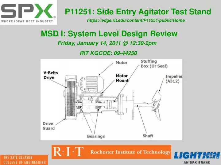
P11251: Side Entry Agitator Test Stand. https://edge.rit.edu/content/P11251/public/Home. MSD I: System Level Design Review. Friday, January 14, 2011 @ 12:30-2pm RIT KGCOE: 09-44250. Project Team/Attendees. Project Sponsor : Richard O. Kehn - "ROK" Senior Technologist - Mixing

E N D
P11251: Side Entry Agitator Test Stand https://edge.rit.edu/content/P11251/public/Home MSD I: System Level Design Review Friday, January 14, 2011 @ 12:30-2pm RIT KGCOE: 09-44250
Project Team/Attendees Project Sponsor : Richard O. Kehn - "ROK" Senior Technologist - Mixing SPX Flow Technology MSD I, Team Guide: William J. Nowak Principal Engineer, BGO/XIG/XRCW/OSL/Media & Mechatronic Systems Xerox Corporation Team P11251: Kurt Lutz: P.M./(Measurement System w/ Integration) Dennis Beatty: (Fluid-Tight Sealing Structure) Joseph Bunjevac: (Physical Structure w/ Adjustability) Daniel Geiyer: (Measurement System w/ Integration) Gregory McCarthy: Scribe/(Motor/Shaft/Coupling Integration)
Meeting Agenda Estimated Time 12:35 - 12:40 12:40 - 12:45 • 12:45 - 1:50 • 12:50 - 12:55 • 12:55 - 1:00 • 1:00 - 1:40 • 1:00 - 1:10 • 1:10 - 1:20 • 1:20 - 1:30 • 1:30 - 1:40 • 1:40 - 1:50 • 1:50 - 1:55 • 1:55 - 2:00 • Mission Statement • Project Description • Review of Customer Needs/Specs • Review of Pairwise, Engineering Metrics, HoQ, Pareto • Concept Sub-System Breakdown • Initial Concept Generation & Selection • Physical Structure • Shaft/Motor/Impeller Integration • Sealing System • Measurement System w/ Hardware Integration • Preliminary Risk Assessment/FMEA • Project Schedule Review (GANTT) • Questions/Comments/Concerns
Mission Statement Mission Statement: To create a side entry agitator test stand that allows the user to measure and calculate axial and tangential components of fluid forces, torque, and impeller speed on the motor, impeller, and shaft, incorporating a wide range of adjustable parameters.
Project Description • Shaft protrudes through the side wall of the tank • very large, under floor tanks where little headroom is available • less costly than top entry mixers • requires less motor torque to agitate the fluid • three to five times the amount of power as a top entry mixer • Rely heavily on impeller selection • different diameters, physical sizes and blade profiles • Previously developed top entry test-rig • they currently have no way to benchmark these same impellers for side entry agitation • Create a test-rig that allows reliable measurement • through a range of adjustability (Impellers/Speeds/etc.) • similar concepts to the top entry test rig • different array of: bending moments, torque and fluid forces • Very beneficial to our customer • benchmark existing and future impeller designs for side entry applications.
Customer Requirements Four Most Important Customer Needs: • Fluid Tight Seal • Calibration Incorporation • Tangential Fluid Forces • Fluid Thrust Force
Pairwise Comparison GraphicalRepresentation of Pairwise Comparison
Pareto Analysis of Eng. Metrics Power Law Distribution By designing for only 40% of the Engineering Metrics, We’ll gain 65% of the advantages of designing for all the Engineering Metrics Top (5) Most Important Engineering Metrics • Tangential Force Measurement • Thrust Force Measurement • Shaft Rotational Speed • Torque Measurement • Ease of Calibration • Time of Calibration
Physical Structure Sub-System Stand Adjustability • Vertical and horizontal adjustment • Depth into tank • Angle left and right • Angle up and down
Physical Structure: Concept Selection Key Advantages • Removes need for tilt plate • Reduces potential issue with structure height • No limit to step increments on any axis • Possibility for fully automated positioning via stepper motors
Shaft, Motor, & Impeller Integration Sub-System Explanation of this sub-system & components: Shaft: Transmits torque & angular velocity via the motor & impeller Coupler: Transmits power between the motor output shaft & shaft Motor: Provides Mechanical Energy to the system Impeller: “Work” horse of the system: agitates the fluid to be mixed Fluid Agitation Impeller Shaft Coupling Motor Tank Wall
SMI: System Diagram w/ Impellers • Given Impeller Dia.: 4.5 – 10” • Off Wall Distance: TYP. 0.5D • <0.4D, Flow Drops Off • >0.5D, Minimal Additional Flow, Adds Cost for Minimal flow benefit • MATL: 316 S.S.
SMI: Shaft Design Selection Shaft Length = APROX. 2.25 – 5”
SMI: Shaft Design Prelim. Equations • Static Cantilever Beam Analysis • Mod-Goodman Shaft Analysis • Natural Frequency Ck
SMI: Shaft to Shaft Coupling Set Screw Shaft Coupling Disc Coupling Gear Coupling • All must have high torsional strength, for accurate fluid force & thrust measurement • Allow for some degree of parallel mis-alignment, to prevent shaft(s) bending • Provide a secure connection between the (2) elements • Long lasting and minimal maintenance/overhaul required LoveJoy Req’s: • 1) Required Max Torque 2) Motor Speed/HP Req. 3) Shaft/Motor Shaft Dia.
SMI: Impeller/Shaft Connection Based on given ID of provided impellers, two conditions could exist: • Shaft Dia. < Impeller Dia. - need for a spacing collar • Shaft Dia. > Impeller Dia. - need for a reducer
SMI: Motor Selection • DC Motor, Variable Drive (per Measurement & Integration) • Highly dependent on “Physical Stand” • Package Size/Weight/Mounting Options • Capable of reaching 1100 RPM under load, with greatest thrust/torque producing impeller • Spec’d based upon required shaft size • Consider Side-Loading Effect on Motor Bearings/Life Side Loading Location
Sealing System: Initial Concepts Concept 2 Concept 1 Concept 3 Concept 4 Concept 5 Concept 6 Concept 7 Concept 8 Concept 9
Sealing System: Final Concept Critical Benefits: • Allows Adjustability • Less parasitic to measured forces • Does not alter tank geometry • Very low leak rate
Axial and Tangential Fluid Force Measurement Concept Generation Load Cell Types: Donut, Pancake, Canister, or Column Mounting Format: Pre-Loaded or Rigid Supporting Structure: Supporting Pins or Load Transfer Arms Pictures from www.lcmsystems.com. Force Load Cell Force or Reaction Load Cell Reaction T=(L1/L2)F Pins resist shear effects.
Axial and Tangential Fluid Force Measurement Concept Evaluation
Axial and Tangential Fluid Force Measurement Concept Selection Three Most Critical Criteria: • Resists Affects of Shear • Measuring Sensitivity • Appropriate Time for Setup Pancake Tension & Compression Load Cell (PTC) Fixed To Test Stand and Motor Bracket Picture From www.lcmsystems.com Side View Isometric View
Torque and RPM Measurement Subsystem Slip Ring: • Electrical connection through a rotating assembly • Low speed limitations • Ring wear and dust brushes impede signal transfer • Requires routine maintenance for cleaning
Torque and RPM Measurement Subsystem Rotary Transformer: • Tolerates high speeds • Non-contact • More accurate • Requires sophisticated signal condition instrumentation • Less tolerant to extraneous loading conditions (bending moments and thrust forces)
Torque and RPM Measurement Subsystem Digital Telemetry: • Software driven allowing changes on the fly • High resolution, sensitivity, and accuracy • More immune to vibration problems • Smaller, lighter, and more compact
Torque and RPM Measurement Subsystem Torque Transducer: • Utilizes a system of strain gauges (Wheatstone Bridge) • Uses slip rings or rotary transformers to power and transfer strain gauge data
Torque and RPM Measurement Subsystem Torque from Motor Constants: • Ideal for direct drive systems • Only requires measurement of motor current
Torque and RPM Measurement Subsystem Critical Criteria • Measurement accuracy and sensitivity • Ease of implementation • Small package size • Allow for multiple shaft diameters • Ease of maintenance
Preliminary Risk Assessment/FMEA https://edge.rit.edu/content/P11251/public/Design%20Documentation
Preliminary Risk Assessment/FMEA Key Risk Items • Full range of adjustability • Seal Effects measurement instrumentation & readings • Sensitivity of Measurement Systems • Successful Integration of Sub-Systems • Orientation affects measurements
Project Plan Review https://edge.rit.edu/content/P11251/public/Team%20Project%20Plan