Download
1 / 10
100 likes | 223 Vues
Study of Deformation due to Thermally Induced Stress in a Water Cooled Plastic Injection Mold A Finite Element Model (FEA) using flexPDE. Craig E. Nelson - Consultant Engineer. Goal for the Numerical Study

E N D
Study of Deformation due to Thermally Induced Stress in a Water Cooled Plastic Injection Mold A Finite Element Model (FEA) using flexPDE Craig E. Nelson - Consultant Engineer
Goal for the Numerical Study A steady state finite element model is to be developed that aids understanding of the stresses and strains in a water cooled steel mold suitable for injection molding thermoplastic parts of moderately large size. The model is “multiphysics” oriented in the sense that stress, strain and temperature fields are cross coupled and solved for simultaneously Plastic polymeric resin is continuously injected through a wedge shaped inlet port at a temperature of 340 degrees C. A rectangular cavity is filled with resin to form the molded part. Two circular cooling pipes in the mold body carry water, which is continuously chilled to 0 degrees C. The temperature differential through the mold cross section causes complex stress and strain fields to result. The strain field will result in distortion of the molded part if not corrected for.
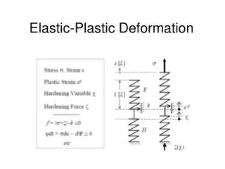
The Cross-Coupled Partial Differential Equations to Be Solved: Temperature and strain equations: dx( sx) + dy( sxy)= 0 dx( sxy)+ dy( sy)= 0 dx(-k*dx( dtemp))+ dy(-k*dy( dtemp)) - source= 0 Stress is subsequently derived from the temperature induced strain field using: sx= C*(ex+ mu*ey- [1+mu]*alpha*dtemp) {sx, sy = x and y direction stress} sy= C*(mu*ex+ ey- [1+mu]*alpha*dtemp) {ex, ey = x and y direction strain} sxy= G*exy {shear stress} where: ex= dx(u) ey= dy(v) exy= dx(v)+ dy(u) and u = x direction strain v = y direction strain C= E/(1-mu^2) G = E/[2*(1+mu)] and E is Young’s Modulus mu is Poison’s ratio alpha is the linear coefficient of expansion
Inlet Injection Port Material is 4140 Steel Cover Plate Mold Body Bottom Plate Cooling Pipe Support Footing The Solution Domain (dimensions are in meters)
Horizontal Strain (dimensions are in meters)
Vertical Strain (dimensions are in meters)
Temperature in the Solution Domain (degrees C)
Temperature in the Solution Domain (degrees C)
Summary A finite element model has been developed that aids understanding of the stresses and strains in a steel mold suitable for injection molding thermoplastic parts of moderately large size. The model is “multiphysics” oriented in the sense that stress, strain and temperature fields are cross coupled and solved for simultaneously