Download
1 / 31
360 likes | 641 Vues
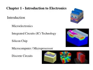
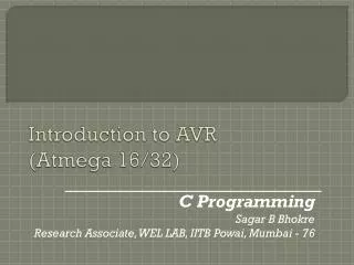
Introduction to AVR Chapter 1. The AVR microcontroller and embedded systems using assembly and c. Topics. Microcontrollers vs. Microprocessors Most common microcontrollers AVR Features AVR members. General Purpose Microprocessors vs. Microcontrollers. Data BUS. General Purpose

E N D
Introduction to AVRChapter 1 The AVR microcontroller and embedded systems using assembly and c
Topics • Microcontrollers vs. Microprocessors • Most common microcontrollers • AVR Features • AVR members
General Purpose Microprocessors vs. Microcontrollers Data BUS General Purpose Micro processor RAM ROM Timer Serial COM Port IO Port Address BUS Control BUS CPU RAM ROM Serial Port Timer I/O • General Purpose Microprocessors • Microcontrollers
Most common microcontrollers • 8-bit microcontrollers • AVR • PIC • HCS12 • 8051 • 32-bit microcontrollers • ARM • PIC32
AVR different groups • Classic AVR • e.g. AT90S2313, AT90S4433 • Mega • e.g. ATmega8, ATmega32, ATmega128 • Tiny • e.g. ATtiny13, ATtiny25 • Special Purpose AVR • e.g. AT90PWM216,AT90USB1287
Let’s get familiar with the AVR part numbers ATmega128 Atmel group Flash =128K ATtiny44 AT90S4433 Atmel Flash =4K Atmel Classic group Tiny group Flash =4K
AVR Architecture (pp 55 - 75)Chapter 2 The AVR microcontroller and embedded systems using assembly and c
Installing Programming tools for ATMEL devices. • Refer to AVRstudioTutorial.pdf in folder \Lecture Notes\E-Books and Reference for tutorial on how to write, compile, and trace a simple program ATmega32 in AVR Studio using Assembly language. • AvrStudio4Setup.exe which is the IDE that allow ATmega32 assembly program to be built, assembled, and simulated for execution, is in the folder \Lecture Notes\AVRStudio4\Installer • Install AvrStudio4Setup.exe first. • Then install AVRStudio4.18SP3.exe to Upgrade • Then Install WinAVR-20100110.exe which is in the folder \Lecture Notes\AVRStudio4\Installer\WinAVR-20100110. • Refer Overview on the AVR Instructions and Directive.pdf in \Lecture Notes\E-Books and Reference folder • Refer page 696 thru 732 of Microcontroller and Embedded Systems E-book in folder \Lecture Notes\E-Books and Reference for AVR Instruction Explained.
Topics • AVR’s CPU • Its architecture • Some simple programs • Data Memory access • Program memory • RISC architecture
AVR’s CPU SREG: CPU ALU R0 R1 R2 … … PC R15 R16 R17 Instruction decoder Instruction Register registers N H Z I S V C T R30 R31 • AVR’s CPU • ALU • 32 General Purpose registers (R0 to R31) • PC register • Instruction decoder
Some simple instructions1. Loading values into the general purpose registers SREG: CPU ALU R0 R1 R2 … … PC R15 R16 R17 Instruction decoder Instruction Register registers N H Z I S V C T R30 R31 LDI (LoadImmediate) • LDI Rd, k • Its equivalent in high level languages: Rd = k • Example: • LDI R16,53 • R16 = 53 • LDI R19,132 • LDI R23,0x27 • R23 = 0x27
Some simple instructions2. Arithmetic calculation SREG: CPU ALU R0 R1 R2 … … PC R15 R16 R17 Instruction decoder Instruction Register registers N H Z I S V C T R30 R31 • There are some instructions for doing Arithmetic and logic operations; such as: ADD, SUB, MUL, AND, etc. • ADD Rd,Rs • Rd = Rd + Rs • Example: • ADD R25, R9 • R25 = R25 + R9 • ADD R17,R30 • R17 = R17 + R30
A simple program SREG: CPU ALU R0 R1 R2 … … PC R15 R16 R17 Instruction decoder Instruction Register registers N H Z I S V C T R30 R31 • Write a program that calculates 19 + 95 LDI R16, 19 ;R16 = 19 LDI R20, 95 ;R20 = 95 ADD R16, R20 ;R16 = R16 + R20
A simple program • Write a program that calculates 19 + 95 + 5 LDI R16, 19 ;R16 = 19 LDI R20, 95 ;R20 = 95 LDI R21, 5 ;R21 = 5 ADD R16, R20 ;R16 = R16 + R20 ADD R16, R21 ;R16 = R16 + R21 LDI R16, 19 ;R16 = 19 LDI R20, 95 ;R20 = 95 ADD R16, R20 ;R16 = R16 + R20 LDI R20, 5 ;R20 = 5 ADD R16, R20 ;R16 = R16 + R20
Some simple instructions2. Arithmetic calculation SREG: CPU ALU R0 R1 R2 … … PC R15 R16 R17 Instruction decoder Instruction Register registers N H Z I S V C T R30 R31 • SUB Rd,Rs • Rd = Rd - Rs • Example: • SUB R25, R9 • R25 = R25 - R9 • SUB R17,R30 • R17 = R17 - R30
R0 thru R15 • Only registers in the range R16 to R31 can be loaded immediate. We cannot load a constant into the registers R0 to R15 directly. It would have to be loaded into a valid register first then copied. To load the value of 10 into register zero (R0): Code: • LDI R16,10 ;Set R16 to value of 10 MOV R0,A ;Copy contents of R16 to R0
Some simple instructions2. Arithmetic calculation SREG: CPU ALU R0 R1 R2 … … PC R15 R16 R17 Instruction decoder Instruction Register registers N H Z I S V C T R30 R31 • INC Rd • Rd = Rd + 1 • Example: • INC R25 • R25 = R25 + 1 • DEC Rd • Rd = Rd - 1 • Example: • DEC R23 • R23 = R23 - 1
Data Address Space LDS (Load direct from data space) LDS Rd, addr ;Rd = [addr] Example: Write a program that stores 55 into location 0x80 of RAM. Example: LDS R1, 0x60 STS (Store direct to data space) Example: What does the following instruction do? LDS R20,2 Example: Write a program that copies the contents of location 0x80 of RAM into location 0x81. Example: Store 0x53 into the SPH register. The address of SPH is 0x5E STS addr,Rd ;[addr]=Rd Example: Add contents of location 0x90 to contents of location 0x95 and store the result in location 0x313. Example: STS 0x60,R15 ; [0x60] = R15 Solution: LDS R20, 0x90 ;R20 = [0x90] LDS R21, 0x95 ;R21 = [0x95] ADD R20, R21 ;R20 = R20 + R21 STS 0x313, R20 ;[0x313] = R20 Solution: LDI R20, 0x53 ;R20 = 0x53 STS 0x5E, R20 ;SPH = R20 Solution: LDI R20, 55 ;R20 = 55 STS 0x80, R20 ;[0x80] = R20 = 55 Answer: It copies the contents of R2 into R20; as 2 is the address of R2. Solution: LDS R20, 0x80 ;R20 = [0x80] STS 0x81, R20 ;[0x81] = R20 = [0x80]
Data Address Space IN (IN from IO location) IN Rd,IOaddress ;Rd = [addr] Example: IN R1, 0x3F ;R1 = SREG IN R17,0x3E ;R17 = SPH OUT (OUT to IO location) Using Names of IO registers Example: Write a program that adds the contents of the PINC IO register to the contents of PIND and stores the result in location 0x90 of the SRAM OUT IOAddr,Rd ;[addr]=Rd Example: OUT SPH,R12 ;OUT 0x3E,R12 IN R15,SREG ;IN R15,0x3F Example: OUT 0x3F,R12 ;SREG = R12 OUT 0x3E,R15 ;SPH = R15 Solution: IN R20,PINC ;R20 = PINC IN R21,PIND ;R21 = PIND ADD R20,R21 ;R20 = R20 + R21 STS 0x90,R20 ;[0x90] = R20
Status Register (SREG) N H Z S V C I T SREG: CPU ALU Solution: $9C 1001 1100 - $9C 1001 1100 $00 0000 0000 R20 = $00 C = 0 because R21 is not bigger than R20 and there is no borrow from D8 bit. Z = 1 because the R20 is zero after the subtraction. H = 0 because there is no borrow from D4 to D3. Solution: 1 $38 0011 1000 + $2F 0010 1111 $67 0110 0111 R16 = 0x67 C = 0 because there is no carry beyond the D7 bit. H = 1 because there is a carry from the D3 to the D4 bit. Z = 0 because the R16 (the result) has a value other than 0 after the addition. Solution: $52 0101 0010 - $73 0111 0011 $DF 1101 1111 R20 = $DF C = 1 because R21 is bigger than R20 and there is a borrow from D8 bit. Z = 0 because the R20 has a value other than zero after the subtraction. H = 1 because there is a borrow from D4 to D3. Solution: $A5 1010 0101 - $23 0010 0011 $82 1000 0010 R20 = $82 C = 0 because R21 is not bigger than R20 and there is no borrow from D8 bit. Z = 0 because the R20 has a value other than 0 after the subtraction. H = 0 because there is no borrow from D4 to D3. Solution: 1 $9C 1001 1100 + $64 0110 0100 $100 1 0000 0000 R20 = 00 C = 1 because there is a carry beyond the D7 bit. H = 1 because there is a carry from the D3 to the D4 bit. Z = 1 because the R20 (the result) has a value 0 in it after the addition. R0 R1 R2 … … PC R15 R16 Instruction decoder R17 Instruction Register registers N H Z I S V C T R30 R31 Example: Show the status of the C, H, and Z flags after the addition of 0x38 and 0x2F in the following instructions: LDI R16, 0x38 ;R16 = 0x38 LDI R17, 0x2F ;R17 = 0x2F ADD R16, R17 ;add R17 to R16 Example: Show the status of the C, H, and Z flags after the addition of 0x9C and 0x64 in the following instructions: LDI R20, 0x9C LDI R21, 0x64 ADD R20, R21 ;add R21 to R20 Example: Show the status of the C, H, and Z flags after the subtraction of 0x23 from 0xA5 in the following instructions: LDI R20, 0xA5 LDI R21, 0x23 SUB R20, R21 ;subtract R21 from R20 Example: Show the status of the C, H, and Z flags after the subtraction of 0x73 from 0x52 in the following instructions: LDI R20, 0x52 LDI R21, 0x73 SUB R20, R21 ;subtract R21 from R20 Example: Show the status of the C, H, and Z flags after the subtraction of 0x9C from 0x9C in the following instructions: LDI R20, 0x9C LDI R21, 0x9C SUB R20, R21 ;subtract R21 from R20 SREG: Carry Interrupt Zero oVerflow Temporary Negative Sign N+V Half carry
Writing Immediate Value to SRAM • You cannot copy immediate value directly into SRAM location in AVR. • This must be done via GPRs • Example: The following program adds content of location 0x220 to location 0x221
Exercise Implement the program that calculates 19 + 95 + 5 on AVR Studio. Use debug and watch the change of the respective registers as you step over through the program. Watch Contents of R16 and check if answer is correct.
Example 2-1 Write the program in AVR Studio to verify that Note: do not forget to add iat the beginning of the program: .include "M32DEF.inc"
Example 2- 2 Verify using AVR Studio