Download
1 / 36
370 likes | 717 Vues
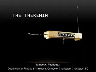
Theremin with Onboard Effects. Patrick Tarantino Shaun Cinnamon Project # 43 ECE 345 - Spring 2001 . Introduction to the Theremin. Invented by Leon Theremin, a Russian physicist Musical signal created from beat frequency of two RF signals

E N D
Theremin with Onboard Effects Patrick Tarantino Shaun Cinnamon Project # 43 ECE 345 - Spring 2001
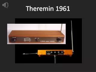
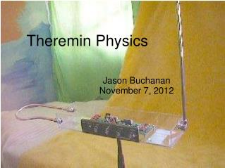
Introduction to the Theremin • Invented by Leon Theremin, a Russian physicist • Musical signal created from beat frequency of two RF signals • Pitch and volume controlled by hand capacitance effects
Basic Design Approach Basic theremin circuit implemented primarily with IC chips • Greatly reduce temperature dependence • Reduce overall circuit cost • Reduce total circuit area required
Design Specifications • Want at least a three octave musical range • Want a good level of sensitivity to hand position change • Want unmodified output and also at least one other “instrument sound”
Tone Control Circuit • Uses two 8038 chips, both with RF outputs, an 8” by 5” square aluminum antenna, and an analog mixer to produce a frequency in the audible range that is controlled by the user’s hand position • Has a base frequency of about 160 kHz, with a range of about 1 kHz
Volume Control Circuit • Uses two 8038 chips, an 8” by 5” square aluminum antenna, a frequency to voltage converter, and an analog mixer to function as an amplifier whose gain is controlled by the user’s hand position • Has a base frequency of about 160 kHz and a range of about 1 kHz
Volume Control Operation • If Vi = Acos(2pft), Vo = k*f • Apply tone signal and this new control signal to an analog mixer, and the mixer now functions as a voltage controlled amplifier
Mixer Operation • Multiplies the signals from the fixed and variable oscillators in both sections • Apply a LPF to eliminate high frequency components, and get output of cos(Dwt), the difference frequency
Complete Theremin Circuit • Tone now controlled with one antenna, volume by the other, and the output signal is ready to be applied to the DSP for digital effects
Wavetable Synthesis Digital Effects for the Theremin
Overview of Wavetable Synthesis • What is a Wavetable? • How are they used? • What is the purpose? • How is Wavetable Synthesis done?
What is a Wavetable? • A Wavetable it a set of samples taken from an actual instrument to simulate the instrument.
How are they used? • The samples are saved into three different Wavetables, along with corresponding amplitude envelopes. • Where do these three different Wavetables come from?
The different Wavetables • The first Wavetable comes from the first 4096 samples of the complete Wavetable. • The second Wavetable comes from the second 4096 samples and the third from the next 4096.
Where are the Amplitude envelopes at? • The amplitude envelopes are located at the end of the table. • They are contained in the next 1500 samples from the end of the wavetables. • Each envelope is 500 samples long.
What happens next? • After the Wavetable and Amplitude Envelopes have been saved into their respective tables they are saved as coefficients to be used in the DSP.
How do we recreate the instrument? • The recreation of the instrument is done by table lookup and by determining the increment through the wavetables.
Table Increment • The table increment can be calculated by this equation: Table Length = 4096 samples Sample Rate = 44100 samples/second Frequency = dependent upon signal from the circuit
What about the amplitude envelopes? • The amplitude envelopes are done in the same manner as the wavetables.
How do we get the frequency of the signal? • We get the frequency of the signal through Zero-Crossing Detection. • Knowing that a sine (or cosine) crosses zero twice per period we can get the number of samples per period.
New Table Increment • The frequency is in samples per period. In order to get the correct table increment a modification was needed. I needed to divide the sampling frequency by the number of samples per period. With the resulting increment being: increment = Table Length / # of Samples
Completion of Wavetable Synthesis • To complete the synthesis we multiply the individual wavetables by the amplitude envelopes and add three tables together to get the synthesized instrument.
How do we change instruments? • A Matlab interface was written to change between the normal Theremin output and the synthesized instrument effects.
Project Build and Testing • DSP configured to amplify input signal • Original mixers used drew too much current, switched to analog mixer IC’s • Maximum value of hand capacitance measured at about 20 pF • Sensing range of antennae begins at about 2 inches from antenna
Project Build and Testing, cont. • Oscillator pairs could not effectively be synched when no hand capacitance was applied • Tried potentiometers to do this, but it was still not precise enough • This problem creates a constant offset frequency which distorts the desired musical range
Project Build and Testing, cont. • Constant offset frequency of about 4 kHz • Volume circuit could not be completed due to problems with the f-to-v converter • Tradeoff between sensitivity to hand capacitance and usable output to f-to-v converter • With the offset frequency, the volume control circuit will not work properly
Successes • Basic volume circuit functional • Input to DSP in proper frequency range and magnitude for alteration • Zero-Crossing Detection detects difference in frequency down 0.1 Hz. • Dividing by number of samples per period • Running multiple instruments
Challenges • 8038 chips limited by a maximum frequency of about 250-300 kHz • Volume circuit not completely functional • Antennas not sensitive enough • Cannot properly synch the oscillator pairs • Running multiple instruments due to limitations in memory • Dividing by a number obtained at run time
Other Possible Tests • Using passive components with greater precision would make the oscillators easier to synch together • Using different materials and shapes for the antennae could make a big difference • Using different method to generate frequencies could improve both synching and sensitivity
Recommendations • Use a different frequency generation method • Design a circuit that will force the two frequencies to equal each other when no hand capacitance is sensed • Consider using an alternative sensing scheme, such as photodetectors