Download

1 / 67
770 likes | 1.07k Vues
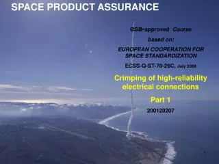
SPACE PRODUCT ASSURANCE. esa- approved Course based on: EUROPEAN COOPERATION FOR SPACE STANDARDIZATION ECSS-Q-ST-70-26C, July 2008 Crimping of high-reliability electrical connections Part 2 20120402. Daniels M22520/5-01 Ferrule shield crimp tool.

E N D
SPACE PRODUCT ASSURANCE esa-approved Course based on: EUROPEAN COOPERATION FOR SPACE STANDARDIZATION ECSS-Q-ST-70-26C, July 2008 Crimping of high-reliability electrical connections Part 2 20120402
5.2 Crimping operations for specific interconnections 5.2.7 Lug and splice wire crimping
5.2 Crimping operations for specific interconnections 5.2.7 Lug and splice wire crimping (continued) 6
5.3 Requirements for new crimp configurations 5.3.1 General
5.3 Requirements for new crimp configurations 5.3.2 Test procedure
5.3 Requirements for new crimp configurations 5.3.2 Test procedure (continued)
5.3 Requirements for new crimp configurations 5.3.2 Test procedure (continued)
5.3 Requirements for new crimp configurations 5.3.3 Sealing and marking
5.4 Test methods 5.4.1 General
5.4 Test method 5.4.2 Voltage-drop
5.4 Test method 5.4.2 Voltage-drop continued……. a simple means of achieving the 14-mm probe spacing! .
5.4 Test methods Table 5-2 Voltage drop test requirements
Test methods 5.4.3 Tensile strength www.twlforce.co.uk
5.4 Test methods 5.4.3 Tensile strength 5.4.3.1 General
5.4 Test methods 5.4.3 Tensile strength 5.4.3.1 General (continued) Ref ECSS-Q-ST-70-26C 5.4.3.2a ‘The required axial strength shall be 75% of the wire strength’ Therefore axial strength requirement= 31.13N ______________________________________________________________________________________________ 18
5.4 Test methods 5.4.3 Tensile strength 5.4.3.1 General (continued) 19
5.4 Test methods 5.4.3 Tensile strength
5.4 Test methods 5.4.3 Tensile strength For example, we could tensile test 10 samples of the shield and then calculate 70% of the average tensile strength. This would be the minimum required tensile strength for the crimp.
5.4 Test methods, Table 5-3 Required ultimate axial strength for compactive and dispersive crimped joints
5.4 Test Methods 5.4.4 Metallography
5.4 Test Methods 5.4.4 Metallography 24
5.4 Test methods 5.4.4 Metallography (continued) i4 Not ‘gas tight’
5.4 Test Methods 5.4.4 Metallography (continued) i5. i6.
5.4 Test methods (voiding <10%) (all wires deformed from circular)
5.4 Test methods 5.4.4 Metallography (continued) (voiding <10%) ‘Springback’ of crimp barrel has resulted in diagonal discontinuities. Solution: use a filler wire to take wire cross-section closer to design maximum of terminal barrel.
5.5 Quality assurance 5.5.1 General
5.5 Quality assurance Fig 5-7 Quality control during crimping operation 30
5.5 Quality assurance 5.5.3 Workmanship
5.5 Quality assurance Insulation clearance < 2mm (when wire diameter is > 16AWG) Insulation clearance <D (when wire is 28AWG up to 16AWG) Figure 5-8: Visible workmanship standards 32
5.5 Quality assurance Figure 5-9 Workmanship examples and crimp microsections 33
5.5.3 Workmanship Heat shrink sleeving correctly installed over connector pin Heat shrink sleeving excessively shrunk over connector pin (this extent of sleeving could also make extraction difficult)
5.5.3 Workmanship Recommended limit of sleeve coverage Sleeving extends too far down connector pin Wire barely visible in inspection hole - reject
5.5.3 Workmanship Supplementary Notes Shrink sleeving is not mandatory for crimped connector contacts unless required by the drawing (it is mandatory in Astrium, often plus encapsulation). It is not used when the crimp barrel is fully recessed in the connector body. It is normally only required in the absence of backshells.
5.5 Quality assurance 5.5.4 Visual inspection 5.5.4.1 Pre-crimp inspection (performed by the operator)a. The operator shall examine the wire for nicks, rings, broken strands, untwisted lay or not‐removed insulation in the area of the crimp before the stripped wire is inserted into the contact or terminal barrel. b. Damaged wires where the base material is exposed shall not be used. c. Contacts and terminal barrels that show evidence of the presence of tarnish, corrosion or physical damage, including bent contacts, shall not be used. d. Inspection shall verify that wire size and type, the contact and terminal are as specified in the drawing or control document. 37
5.5 Quality assurance 5.5.4 Visual inspection (continued) 5.5.4.2 Post-crimp inspection (performed by quality assurance) a. The QA inspector shall carry out inspection with the aid of a binocular microscope having an initial linear magnification of ×7. NOTE Further examination of surface characteristics can be performed at higher magnifications. b. The inspector shall not physically disturb parts and conductor leads to aid inspection. 38
5.5 Quality assurance 5.5.4 Visual inspection (continued) 5.5.4.2 Post-crimp inspection (performed by quality assurance) c. The following acceptance criteria shall be met; 1. Insulation is not damaged by the crimping tool or the terminal; 2. The conductor is visible in the inspection hole when an inspection hole is provided; 3. The crimp barrel has no unintentional sharp edges, peeled metal, burrs, cracked platings or cuts after crimping; 4. All functional parts, including all retention clips or locking devices, are operational after the crimp has been made; 5. No tarnished or corroded contacts are present; 39
5.5 Quality assurance 5.5.4 Visual inspection (continued) 5.5.4.2 Post-crimp inspection (performed by quality assurance) 6. No misplaced crimps, as determined by marks found on areas not designed to take crimping, are present; 40
5.5 Quality assurance 5.5.4 Visual inspection (continued) 5.5.4.2 Post-crimp inspection (performed by quality assurance) 7. No undercrimps or overcrimps are present; NOTE An undercrimp is detected by a loose conductor and an overcrimp by broken strands or deformed wire at end of terminal. 8. If undercrimps or overcrimps are detected this is cause to stop operations at that station, reject all production crimps made since the last verification or pull test, investigate tool, wire and terminals for the cause of failure. 9. No bent contacts are present. d. Failure to meet the acceptance criteria of 5.5.4.2c shall be cause for rejection. 41
5.5 Quality assurance 5.5.5 Shift performance inspection and test a. Each operator shall prepare four samples at the beginning of a shift or before a series of crimping operations. b. At the end of the operation four further samples shall be crimped. c. Alternatively the supplier shall keep a logbook for each tool. d. The logbook shall show the quantity of parts crimped since each calibration and since each go/no-go operation. e. Four samples shall be crimped after each 100 crimping operations have been performed. 42
5.5 Quality assurance 5.5.5 Shift performance inspection and test f. A tool shall be changed whenever a wire size or contact size is changed. g. The operator shall prepare four samples at the start of the operation after such a change. NOTE This can be omitted if samples have already been prepared by the tool during the shift. 43
5.5 Quality assurance 5.5.5 Shift performance inspection and test (continued)h. In each case, the operator shall submit three samples to the tensile strength test detailed in clause 5.4.3. i. The fourth sample shall be retained for reference and traceability purposes (in conformance with clause 5.5.6.2 requirements). j. The supplier shall perform an analysis of shift performance test results, in comparison with initial tool calibration results, to determine any drift in tool performance. 44
5.5 Quality assurance 5.5.6 Calibration of crimping tools5.5.6.1 General a. The QA organization of the supplier shall ensure that each crimping tool and piece of measuring equipment is calibrated as indicated in the subsequent sub clauses. b. The QA organization of the supplier shall record any suspected and actual equipment failure as a project nonconformance report NOTE Based on past nonconformance reports previous results can be examined to ascertain whether or not re-inspection or retesting is required. c. The QA organization of the supplier shall notify the customer of the nonconformance details. d. The supplier’s calibration procedure shall include the requirements specified in this clause for tool calibration. 45
5.5 Quality assurance 5.5.6 Calibration of crimping tools(continued)5.5.6.2 Validation a. The QA organization of the supplier shall ensure that crimping tools, both manual and powered, are calibrated when initially set up for each specific wire size, connection size and type prior to first use. b. Calibration shall be verified in conformance with the following check-list: 1. cleanliness control of the active part of the tool (e.g. indenters);2. set up with the aid of the “go/no‐go” gauge in conformance with specified conditions; 3. tests in conformance with the clause 5.4 requirements on not less than four samples. 46
5.5 Quality assurance 5.5.6 Calibration of crimping tools(continued)5.5.6.2 Validation (continued)c. After satisfactory calibration the tool status shall be documented in a “tool calibration sheet” to ensure tool traceability. d. This traceability shall be established by periodic analysis of the corresponding data from the shift performance inspection and tests (in conformance with clause 5.5.5 requirements), NOTE The frequency of analysis is defined in relation to production activity such as six months or 2 500 crimping operations. e. A significant drift in test results shall result in tool rejection. NOTE Such a tool is generally labelled ‘out-of-calibration tool’ (in conformance with clause 5.5.6.4 requirements). 47
Statistics • Mean 4 pull strength values: 81N, 81N, 78N, 80N Mean = 320/4 = 80 N • Standard deviation Find the differences from the mean: 1, 1, 2, 0 Square the differences: 1, 1, 4, 0 Add the squares of the differences: 1 + 1 + 4 + 0 = 6 Divide by (n-1), ie 6/(4-1) = 2 This is called the Variance. Standard deviation =Övariance = Ö2 1.414 and next…..Process Capability
Statistics Process Capability (Cpk, Cpu or Cpl) This tells us whether a process, given its natural variation, is capable of producing parts within specification. Cpk is the process capability of a process with upper and lower specification limits (USL & LSL). Cpu is the process capability of a process with only an upper specification limit (USL). Cpl is the process capability of a process with only a lower specification limit (LSL).