Download
1 / 32
320 likes | 513 Vues
ENG2000 Chapter 6 Forces and Structures. Overview. We would like to apply our increased understanding of the microscopic properties of materials to larger scale structures This branch of engineering is called statics because nothing is supposed to move

E N D
Overview • We would like to apply our increased understanding of the microscopic properties of materials to larger scale structures • This branch of engineering is called statics • because nothing is supposed to move • We will briefly review forces, moments and couples • As well as equilibrium and the free body diagram • From there, we can consider more complex issues, such as trusses and beams • This is a brief overview of a large field • and we can only touch a small part of the total subject
Where you’ve seen some of this before • Phys1010 covers • forces, vectors and motion • equilibrium and elasticity • See Halliday, Resnick and Walker Chs 2 – 6 & 13 • While we will give a brief reminder here, it is assumed that you know this material already
Forces • Force are vectors • in order to be fully described, the magnitude and direction of a force is required • There are three types of vectors • free vector – has a magnitude and direction, but its line of action does not pass through a unique position in space (e.g. all points in a car have the same velocity) • sliding vector – has a unique magnitude, direction and its line of action passes through a unique point, but the point of application of the force can be anywhere along the line of application (e.g. horizontally pushing or pulling a car) • fixed vector – a vector with a specific point of application (e.g. a load on a beam)
Transmissability • In all the cases considered in this course, we will assumed that bodies are rigid • no forces are generated within the body • Hence, it is assumed that forces are transmitted perfectly through the body • “the external effect of a force on a body is the same for all points of application of the force along its line of action” • It should be noted that this refers to the external effect • internally, the microscopic response of the body might be quite different forces have the same effect
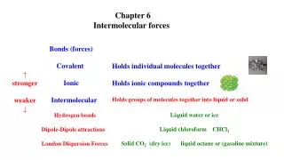
Types of force • A number of classifications of forces can be drawn • Contact (physical pull) versus non-contact (e.g. gravity) • Point forces versus distributed forces
The lines of actions of forces due to ropes attached to an eyelet are considered to pass through the same point Such force systems are termed concurrent Concurrent force systems can be replaced by a single resultant force These forces are coplanar These forces are collinear
A O MO = Fd (moment is a vector quantity) MO d O F A F Moment • Any force that is not through the centre of mass of an object causes a tendency to rotation of the object about some axis • The moment of the force, F, about O is a measure of the tendency to rotation about axis A–A • which is perpendicular to the plane containing F and O O is the moment centre d is the moment arm A–A is the moment axis
The original Starship Enterprise has engines that clearly do not pass through the centre of mass. The resulting moment would cause the ship to rotate This was fixed for NCC1701d http://www.cs.umanitoba.ca/~djc/startrek/pics/BigEnPlanet.gif http://www.research.ibm.com/people/d/dfb/trek/ncc1701.jpg
O a a R d h b A b B Principle of moments • States that the moment of the resultant of a system of forces is equal to the vector sum of the moments of the individual forces • about the same point or axis MR = Rd = R(h cos g) MA = Aa = A(h cos ) MB = Bb = B(h cos ) also Rcosg = Acosa + bcosb substituting for the cos’s from the top three expressions and multiplying through by h gives: MR = MA + MB
Centre of Mass • For any object or collection of objects, there is a location at which all the mass can be thought of as being concentrated • so a force acting through this centre of mass will cause no rotation • On earth for objects small compared with the earth’s curvature, the centre of gravity is essentially identical to the centre of mass • A similar concept applies to geometrical shapes (lines, areas, volumes), but the term is centroid • because a shape has no physical existence
elemental mass at x, y, z z G y zcom mg xcom gdm ycom x Calculating centre of mass • To derive the centre of mass, we make use of the definition of centre of gravity • the moment of the entire body (i.e. at COG) around an axis is equal to the sum of all the moments of the elemental masses comprising the body • we assume that COG and centre of mass are the same, so we can divide through by g About y-axis: Moment of whole body is = mgxcom Moment of all elements = g∫x dm Hence xcom = (∫x dm)/m Similarly: ycom = (∫y dm)/m zcom = (∫z dm)/m
F d MO = Fd provided O is in thesame plane as the couple O F Couple • A couple consists of two equal, non-collinear forces that are anti-parallel • i.e. opposite directions • The net force in any direction is zero, so a couple gives rise to ‘pure’ rotation
Equilibrium of a particle • We will consider only particles in equilibrium • vector sum of all external forces = resultant force = 0 • a body is called a particle when its shape and size have no influence on the problem • Typically, the system to be analysed consists of a number of interacting bodies/particles • To isolate the one of interest, we draw a free body diagram of just that object • this diagram includes all the external forces on the body of interest, whether directly applied to it or resulting from interaction with the other bodies (not shown on the FBD) • Constructing the FBD requires two main steps …
Free body diagram • 1. Decide which body to isolate and sketch the external boundary around that object • 2. Draw all the forces (including unknowns) with vectors in their correct positions • forces at interfaces between objects are assumed only to act normal to the surface (since we assume no friction) • ropes, chains, etc are deemed to be totally flexible (hence transmit only axial forces) • See examples …
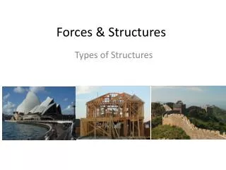
Structures • We now have some basic tools to use on the analysis of simple structures • A structure can be thought of as a system of free bodies held in equilibrium • so a structure must be dismantled in order to examine the internal forces • First we will look at plane trusses • e.g. some bridges, the frames that support the house roof • Then we will consider concentrated loads on beams • before moving on to distributed loading • In all cases, the structures will be statically determinate • i.e. sufficient is known in order to solve for all the unknowns
Warren truss • For an informative look at different types of bridge and roof trusses, see • http://pghbridges.com/basics.htm • http://www.trussed-rafters.co.uk/ttypes.htm http://www.aku.ac.ir/faculty1/aliniamm/Structural%20Slides/trusses/p/IMG0009.jpg
Pratt truss http://www.bcsj.org/rr/bcsj/trackplan/bcsj_ver_17/MillCity/pix/pinpratt_01_m.jpg http://www.aku.ac.ir/faculty1/aliniamm/Structural%20Slides/trusses/p/IMG0005.jpg
Other trusses http://www.kamloopsjunction.com/howe_tsa.jpg http://icampus1.mit.edu/2.973/images/Baltimore_bridge.jpg
Assumptions for truss calculations truss members are connected by frictionless pins – no moment members are weightless provides vertical & horizontal support but no moment provides vertical support but no moment or horizontal force loads only applied to ends of members
TAB TBC P P B TAB TBC TAB TBC C A TAC TAC Ax Ay Cy TAC TAC Simple analysis
It is important to identify which members are in tension and which in compression • long, thin truss members are relatively weak in compression and tend to buckle • they need to be identified and strengthened if necessary • The roller support not only allows for expansion of the structure • it removes one unknown – the horizontal reaction – to make the structure determinate • Trusses are regarded as rigid if they maintain their shape if the supports are removed non-rigid rigid
Method of joints • The diagram on the previous slide was an example of the method of joints • the structure is ‘exploded’ and the forces on each member and joint are identified • the equilibrium analysis of each joint gives enough simultaneous equations to solve for unknowns • it’s really the ‘brute force’ approach • There are several conventions • initially we assume all members are in tension – if it turns out they are in compression, the sign (direction) will tell us so • we also draw the arrows as if members are in tension • forces are labelled e.g. TAC regardless of whether they go from A to C or C to A • Choose a joint with few unknown forces to start
TCB C TCD P A B C D E Zero-force members • Frequently the analysis can be simplified by identifying members that carry no load • two typical cases are found • When only two members form a non-collinear joint and there is no external force or reaction at that joint, then both members must be zero-force If either TCB or TCD ≠ 0, then C cannot be in equilibrium, since there is no restoring force towards the right. Hence both BC and CD are zero-load members here.
B TAB TBC TBD • When three members form a truss joint for which two members are collinear and the third is at an angle to these, then this third member must be zero-force • in the absence of an external force or reaction from a support P Here, joint B has only one force in the vertical direction. Hence, this force must be zero or B would move (provided there are no external loads/reactions) Also TAB = TBC A B C D E
While zero-force members can be removed in this configuration, care should be taken • any change in the loading can lead to the member carrying a load • the stability of the truss can be degraded by removing the zero-force member P You may think that we can remove AD and BD to make a triangle … This satisfies the statics requirements However, this leaves a long CE member to carry a compressive load. This long member is highly susceptible to failure by buckling. A B C D E
Method of sections • When the truss exceeds a certain size, the method of joints becomes unnecessarily tedious • If the joints are in equilibrium, so too is the truss as a whole • Hence, we can also split it into two equilibrium part-trusses • provided we apply the appropriate forces to the cut ends • and we can draw an individual free body diagram for the two parts, including the external and reaction forces • We can cut up to three members and still have enough equations to solve for the six unknowns • the three reactions from the supports • and the three forces in the members
If no cut can be made through three or fewer members and which also passes through the member of interest • then the method of joints must be used • The method of sections is especially useful to find the force in a beam in the middle of a large truss • when lots of joints must be analysed to get the same result • and errors made in calculations for each joint will propagate, possibly giving an unacceptably inaccurate result
Summary • We have now followed a path from atomic bonding, through material properties and basic mechanical relations to an understanding of complex engineering structures • In the next step, we look in more detail at the beams that comprise the trusses • in particular, we are interested in how forces are transmitted though beams • and what effect the beam shape has on the strength