Download
1 / 1
10 likes | 141 Vues
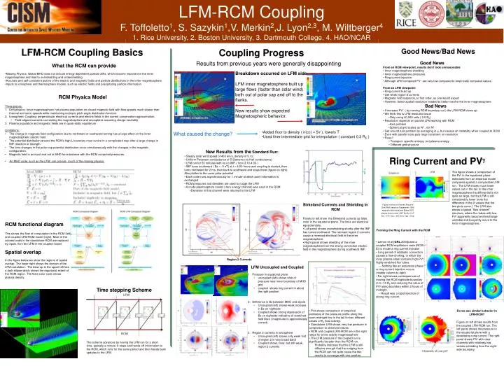
LFM-RCM Coupling F. Toffoletto 1 , S. Sazykin 1 ,V. Merkin 2 ,J. Lyon 2,3 , M. Wiltberger 4 1. Rice University, 2. Boston University, 3. Dartmouth College, 4. HAO/NCAR. LFM-RCM Coupling Basics. Coupling Progress. Good News/Bad News. Results from previous years were generally disappointing.

E N D
LFM-RCM Coupling F. Toffoletto1, S. Sazykin1,V. Merkin2,J. Lyon2,3, M. Wiltberger4 1. Rice University, 2. Boston University, 3. Dartmouth College, 4. HAO/NCAR LFM-RCM Coupling Basics Coupling Progress Good News/Bad News Results from previous years were generally disappointing • Good News • From an RCM viewpoint, results don’t look unreasonable • Inner magnetosphere shielding • Inner magnetosphere pressures • Ring current injection • Although LFM computed PVg are very low compared to empirically computed values • From an LFM viewpoint: • Ring current build up • Get weak region-2 currents • Magnetic field responds, to first order, as one would expect • However, better spatial resolution needed to better resolve the inner magnetosphere • Bad News • If increase PVg ( by moving RCM boundary out ) the LFM-RCM blows up. • We think this is LFM resolution issue • Only using 40,000 cells ( 0.5 RE) • Resolution depends on parallel LFM working with RCM • Axis problem • Spherical grid scales as N5 , not N4 • Get around axis problem by averaging in j, but causes an instability when coupled to RCM • Even with parallel code puts large constraint on resolution • Fixes? • Transport specific entropy ,not plasma energy • Different grid structure • What the RCM can provide • Missing Physics: Global MHD does not include energy dependent particle drifts, which become important in the inner magnetosphere and lead to overshielding and undershielding • Accurate and self-consistent picture of the electric and magnetic fields and particle distributions in the inner magnetosphere • Inputs to ionosphere and thermosphere models, such as electric fields and precipitating particle information Breakdown occurred on LFM side LFM inner magnetosphere built up large flows (faster than solar wind) both out of polar cap and off to the flanks. New results show expected Magnetospheric behavior. • RCM Physics Model • Three pieces: • Drift physics: Inner magnetospheric hot plasma population on closed magnetic field with flow speeds much slower than thermal and sonic speeds while maintaining isotropic pitch-angle distribution function. • Ionospheric Coupling: perpendicular electrical currents and electric fields in the current conservation approximation. • Field-aligned currents connecting the magnetosphere and ionosphere assuming charge neutrality • Plasma population and magnetic fields are in quasi-static equilibrium • Limitations: • The change in magnetic field configuration due to northward or southward turning has a large effect on the inner magnetospheric electric field. • The potential distribution around the RCM’s high-L boundary must evolve in a complicated way after a large change in IMF direction or strength. • The time changes in the polar-cap potential distribution occur simultaneously with the changes in the magnetic configuration. • Magnetic field is an input and not in MHD force balance with the RCM computed pressures. • An MHD code, such as the LFM, can provide much of the missing physics: • Added floor to density ( n(cc) = 5/r ), lowers T • Used finer intermediate grid for interpolation ( constant 0.3 RE ) What caused the change? • New Results from theStandard Run: • Steady solar wind speed of 400 km/s, density of 5 /cc • Uniform Pedersen conductance of 5 Siemens (no Hall conductance) • LFM run for 50 minutes with no no IMF ( from 3:10-4:00 ) • IMF turns southward ( Bz = -5 nT) at t = 4:00 hours and coupling is started, then turns northward for 2 hrs, then back to southward and stays there (figure on right). Also plotted is the cross polar potential • Each code runs asynchronously for 1 minute at which point information is exchanged • RCM pressures and densities are used to nudge the LFM • A crude plasmasphere model ( zero energy channel) was used in the RCM • Densities in that channel were returned to the LFM Ring Current and PVg The figure shows a comparison of the PVg in the equatorial plane estimated from an empirical model compared against a comparable LFM run. The LFM shows much lower values out in the tail. In the inner magnetosphere the differential is not quite so large, but the LFM is still considerably lower (note the difference in the X values that the two plots cover.) The LFM also shows a typical “flow channel” structure, where flux tubes with low PVγapparently become interchange unstable and buoyantly move to the Inner magnetosphere. Birkeland Currents and Shielding in RCM Figure courtesy of Xiaoyan Xing and Dick Wolf, based on Tsyganenko 1996 magnetic field model and Mukai 2003 plasma sheet model. (IMF Bx=By=5 nT, Bz= -5 nT, vsw = 400 km/s, nsw = 5/cc) • Panels to left show the Birkeland currents as false color in the equatorial plane. The lines are electrical equipotentials. • Left panel shows overshielding shortly after the IMF has turned northward. The remnant region 2 currents cause a reversed electrical field in the inner magnetosphere. • Right panel shows shielding of the inner magnetosphere from the strong convection electric field in the magnetosphere during southward IMF. RCM functional diagram This shows the flow of computation in the RCM (left) and coupled LFM-RCM model (right). Most of the colored ovals in the standalone RCM are replaced by inputs from the LFM in the coupled model. Spatial overlap In the figure below we show the regions of spatial overlap. The lower right shows the domain of the LFM calculation. The blow-up in the upper left has a dark ellipse which shows the equatorial extent of the RCM region. The false color code shows plasma density. Forming the Ring Current with the RCM • Lemon et al [GRL,2004]used a coupled RCM equilibrium code (RCM-E) to model a ring current injection • Long period of adiabatic convection causes a flow-choking, in which the inner plasma sheet contains high-PVγ, highly stretched flux tubes. • -- Nothing like an expansion phase or ring-current injection occurs (middle column to right) • Far right shows consequences of moving the RCM nightside boundary in to -10 RE and reducing the value of PVγalong boundary within 2 hours of midnight. • -- Result was a rapid injection of strong ring current. Region 2 Currents LFM Uncoupled and Coupled • Pressure in equatorial plane • uncoupled (left) shows blob of pressure near inner boundary of MHD grid. • coupled shows ring current in about the right position • Difference in Bz between MHD and dipole • Uncoupled (left) shows weak increase in Bz on nightside • Coupled shows strong depression of Bz on nightside indicative of stretched field lines ( magnitude is approximately correct) • Region 2 currents in ionosphere • Uncoupled (left) shows only weak hint of region 2 in very broad band • Coupled shows clear, but still weak, region 2 currents Time stepping Scheme • Plot shows comparison of empirical estimates of the pressure profile along the noon-midnight line in the tail for two different values of Kp (low activity). • Standalone LFM shows very low pressure in comparison to observed values • RCM and coupled LFM-RCM are in the right range for a low activity magnetosphere • The LFM pressure in the coupled run is significantly broader than the RCM run. • Probably indicates that the LFM is still diffusive enough that the nudging from the RCM can not quite cause the two results to converge with one another. Do we see similar behavior in LFM-RCM? Figure on left shows results from the coupled LFM-RCM run. The left panel shows the pressure in the equatorial plane with a developing rung current. The right panel shows PVγwith clear channels with relatively low values extending from the night-side boundary. The scheme advances by having the LFM run for a short time, typically a minute. It stops and hands off information to the RCM, which runs for the same period and then hands back updates to the LFM.


![Statistics [1/2,3/2]](https://cdn2.slideserve.com/4297614/statistics-1-2-3-2-dt.jpg)