Download
1 / 86
860 likes | 1.12k Vues
Non traditional Machining Process. Presented By Bidve M.A. Introduction. In this chapter we are going to discuss the non traditional machining processes or non conventional machining processes. The traditional process are not suitable for the machining in following cases.

E N D
Non traditional Machining Process Presented By Bidve M.A.
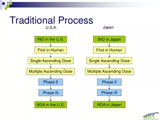
Introduction • In this chapter we are going to discuss the non traditional machining processes or non conventional machining processes. • The traditional process are not suitable for the machining in following cases. 1. Workpiece materials of greater hardness. 2. Materials with high strength, heat resistance such titanium & alloys, etc. 3. Complex and intricate shapes with high accuracy.
Definition of Non-traditional Machining Process • It is defined as a group of processes that remove excess material by various techniques involving mechanical, thermal, electrical or chemical energy or combination of these energies without use of sharp cutting tools which are required in traditional machining processes.
Need for Non-traditional Machining Process • As the world is advancing forth technically in the field of space research, missiles and nuclear industry very complicated and precise components are demanded by the above fields. • High Strength Alloys. • Complex Surface. • High Accuracy and Surface Finish. • Technology Advancement.
High Strength Alloys: The extreme hard alloys like titanium, super alloys are difficult to machine as hardness is more than cutting tool material. • Complex Surface: The intricate shape of components like dies, moulds are difficult to machine as they are made from hardened steel. Long holes of small size are difficult to machine.
High Accuracy and Surface Finish: The accuracy and surface finish in hard materials can not possible through conventional machining. It is costly and practically not feasible. • Technology Advancement: New exotic material as well as innovative geometric design of products and components leads to development of new process.
Application of Non-traditional Machining Process • Intricate Shaped Blind Holes: It is used for machining blind holes like square hole of 15mm X 15mm with a depth of 30mm. • Difficult to Machine Material: It is used to machine alloys, carbides, etc. • Deep Holes of Small Size: Small diameter hole of 1.5 mm size with length of 30mm(l/d=20)
4. Low Stress Grinding: Electrochemical grinding gives minimum stress during grinding compared to conventional grinding. 5. Machining of Composites: Composites are combination of metals and non-metals and difficult to machine by conventional methods.
Advantages of Non-traditional Machining Process • Applicable to all materials: These methods are not affected by hardness, toughness and brittleness of work materials. • Intricate Shape Machining: It can produce complex-intricate shape on any workpiece material. • Extreme Hard Material Machining: Hard to machine material like tungsten, uranium, tantalum can be machined.
4. No Mechanical Contact: Material is removed without mechanical contact with the workpiece material. 5. Easy Compatible: It can be combined with CNC and minicomputer controls for automation. 6. High Accuracy: High accuracy to close tolerance is easily obtained in these methods.
Classification of Non-traditional Machining Process Non-traditional Machining Process Mechanical Processes AJM USM WJM AWJM Chemical Processes CHM PCM Electrochemical Processes ECM ECG EJD Electrothermal Processes EDM LBM PAM EBM IBM
Abrasive Jet Machining(AJM) • It is the mechanical method of metal removed by using sharp edged abrasive striking on a workpiece surface with high speed. • AJM can effectively machine hard and brittle materials like glass, silicon, tungsten and ceramics, refractory materials, super alloys, etc. • This process is not suitable for softer material such as rubber and plastics.
Principle of AJM • The fundamental principle of this process involves the use of a high speed stream of abrasive particles carried by a high pressure air/gas on the work surface through a nozzle. • The metal removal occurs due to erosion caused by the abrasive particles impacting the work surface at a high speed. • With repeated impact of abrasive, small bits of material get loosened and a fresh surface is exposed to the jet. • The abrasive particles carried by high pressure gas/air at a velocity of 200 to 400 m/sec and standoff distance between nozzle tip and workpiece is kept about 0.7 to 1 mm. As the distance increases, the MRR increases max upto 12mm.
1. Nozzle • The nozzle is the conical shaped pipe or tube. It increases the velocity of the mixture of gas and abrasive particles. • It is made of tungsten carbide and sapphire as it is subjected to wear due to high velocity of abrasives. • Tungsten carbide nozzle can be made in circular rectangular or square cross section. • The life of tungsten carbide is around 12-30hrs and sapphire is around 300 hrs.
2. Abrasive Powder • The abrasive particles should have irregular shape and consists of short edges. The rounded shape will be useless. • The abrasive generally are aluminum oxide, silicon carbide, glass powder, sodium bicarbonate, dolomite, glass blades, etc. • The average size of abrasive particles are vary from 10 to 50 microns. Larger sizes are used for rapid removal rate while smaller sizes are used for good surface finish and precision work.
2. Abrasive Powder • The abrasive particles generally not used again and again because cutting edges are damaged. • The abrasive powder must be kept dry, mist powder may clog the nozzle. • The optimum abrasive flow rate is 8-18 gram/min. • Weight of abrasive should be one third the weight of air flowing.
3. Gas/ air Supply • The gas used for carrying abrasive along with it may be air, nitrogen or carbon dioxide. oxygen never used as it may cause fire hazard. • The pressure required for the gas ranges from 2 to 8 kg/cm2. • The velocity of gas coming out from the nozzle is 300m/s. • Higher nozzle pressure results in greater material removal rate but it decreases the nozzle life.
4. Mixing Chamber • It is the chamber in which gas under pressure is mixed with abrasive powder in the required quantity. • The abrasive powder feed rate is controlled by the amplitude of vibration of the mixing chamber.
Advantages of AJM • AJM provides cool cutting action. Very less amount of heat is produced during process. • It has ability to cut delicate and heat sensitive materials without any damage. • The process is free from vibration as there is no contact of the tool and workpiece. • The capital cost is low. • The process has the ability to cut intricate shaped holes in hard brittle materials.
Disadvantages of AJM • MRR is slow and its application is limited. • The machining accuracy is poor. • Nozzle wear rate is high. • It is not suitable for machining ductile materials. • The abrasive powder used in the process can not be reused.
Application of AJM • Debarring, etching and cleaning of hard and brittle materials, alloys and non metals. • Machining brittle and heat sensitive materials like glass, quartz, ceramics, etc. • It is used for drilling holes, cutting slots, cleaning hard surfaces, polishing, etc. • Frosting and abrading of glass articles. • Trimming of resistors used in hybrid power amplifier circuits.
Water Jet Machining(WJM) • Dr. Norman Franz is regarded as the father of the water jet. He was the first person to study the use of high pressure water as a cutting tool. • The water jet is nothing but passing the water in small diameter nozzle to increase its velocity. The high velocity of water jet with twice speed of sound strikes on the workpiece removes material easily.
Water Jet Machining(WJM) • A high pressure, high velocity jet of water has two properties which makes it useful in machining. • Destructive Power 2. Precision cutting tool Types of water jets: i) Pure water jet ii) Abrasive water jet In pure water jet only water is used under high pressure and velocity for cutting soft materials with low cutting force.
Water Jet Machining(WJM) • In abrasive jet the abrasive particles with water are accelerated and removes metal from the surface. They are more powerful than pure water jet. They are useful for cutting hard materials such as metals, stone, composites and ceramics.
Principle of WJM • It involves the use of high velocity water jet to smoothly cut a soft workpiece. It is simlar to AJM. • In WJM high velocity water jet is allowed to strike a given workpiece. During this process its kinetic energy is converted into pressure energy. This induces a stress on the workpiece and due to that unwanted particles automatically removed from workpiece.
Principle of WJM • WJM is used during fabrication of machine parts. It is preferred method when the materials being cut are sensitive to the high temperature generated by other methods.
Construction of WJM • Reservoir: It is used for storing water that is to be used in the machining operation. • Pump: It pumps the water from the reservoir. • Intensifier: It is connected to the pump. It pressurizes the water acquired from the pump to a desired level. • Accumulator: It is used for temporarily storing the pressurized water. It is connected to the flow regulator through control valve.
Construction of WJM • Control valve: It controls the direction and pressure of pressurized water that is to be supplied to the nozzle. • Flow regulator: It is used to regulate the flow of water. • Nozzle: It converts the pressurized water as a water jet at a high velocity. It has orifice diameter varies from 0.08mm to 0.5mm and exit velocity is 920m/sec.
Working of WJM • Water from the reservoir is pumped to the intensifier using a hydraulic pump. • The intensifier increases the pressure of the water to the required level upto 200-400Mpa. • Pressurized water then send to accumulator. The accumulator temporarily stores the pressurized water. • Pressurized water then enters the nozzle by passing through the control valve and flow regulator.
Working of WJM • Control valve controls the direction of water and limits the pressure of water under permissible limits. • Flow regulator regulates and controls the flow rate of water. • Pressurized water finally enters the nozzle. It expands with a tremendous increase in its kinetic energy. High velocity water jet is produced by the nozzle.
Working of WJM • When this water jet strikes the workpiece, stresses are induced. These stresses are used to remove material from the workpiece. • The water used in water jet machining may or may not be used with stabilizers. Stabilizers are substances that improve the quality of water jet by preventing its fragmentation.
Advantages of WJM • Water is cheap, non toxic, easily available and can be disposed easily. • Water jet machining is a relatively fast process. • It prevents the formation of heat affected zones on the workpiece. • It automatically cleans the surface of the workpiece
Advantages of WJM • WJM has excellent precision. Tolerances of the order of _+ 0.005” can be obtained. • It does not produce any hazardous gas. • It is eco-friendly. • The burr produced is minimum. • Cut can be started at any location without need of predrilled holes.
Disadvantages of WJM • Only soft materials can be machined. • Very thick materials can not be easily machined. • Initial investment is high. • Not suitable for mass production because of high maintenance requirement.
Application of WJM • Water jet machining is used to cut thin non-metallic sheets. • It is used to cut rubber, wood, ceramics and many other soft materials like paper boards, plastics, asbestos, fiber glass, leather, etc. • It is used for machining circuit boards. • It is used in food industry. • Cutting rocks, debarring, removing deposits from surface.
Electro Discharge Machining(EDM) • It is also called as spark erosion, electro erosion or spark machining. • It is non traditional machining process based on the principle of erosion of metals by an interrupted electric spark discharge. These discharges are repeated many thousand times/sec in the selected area of workpiece. • In this method, all operations are carried out in a single setup. It can be applied to machine steels, super alloys, refractory's, etc.
Definition of EDM • Electro discharge machining is an electro-thermal non traditional machining process, where electrical energy is used to generate electric spark and material removal mainly occurs due to thermal energy of the spark. • EDM is used to machine complex material, high strength temperature resistant alloys, used for making stamping tools, wire drawing and extrusion dies, intricate mould cavity, etc.
Principle of EDM • It works on the principle of metal removal by using combination of electrical and thermal energy. The electrical energy is utilized to create electrical spark and heat is produced for erosion of metal.
Principle of EDM • The workpiece or job is connected to the positive terminal of the electric source and it acts as an anode. The tool electrode is connected to the negative terminal to acts as a cathode. • The tool and workpiece is separated by a spark gap of about 0.01 to 0.50mm. This spark gap is allowed to force or immerse by nonconductive dielectric fluid.
Principle of EDM • Suitable electrical input is applied between tool and workpiece, it creates spark due to small gap. • The electric energy is discharged in the gap and causes breakdown of the dielectric. • Shock waves in the dielectric are created and the impact of electrons on the work material causes pressure about 1000kg/cm2. • It creates a high temperature about 11000C and the metal melts instantaneously.
Working of EDM • Tool electrode and workpiece: Tool electrode has the shape basically same to that of the product desired with allowance for side clearance and over cut. The tool provided with hole drilled at the centre to pump the dielectric fluid. The workpiece to be machined is mounted on the base of the machine with suitable fixture. The workpiece is connected to positive terminal of the D.C. power supply.
Working of EDM 2. Dielectric Fluid: The dielectric fluid is a spark conductor, coolant and also a flushing medium. The common dielectric fluid used are paraffin oil, transformer oil and kerosene. Dielectric fluid is stored in a tank and circulated through a pump with the help of nozzle at the gap between tool and workpiece.
Working of EDM 3. Electric Power Supply and Spark Generator: The D.C. power supply with current density in the range of 10000 A/cm2 and the power density of 500 mw/cm2 is used. The voltage is about 40-450 volts is applied. Spark generator is the circuit consists of RC combination. This circuit helps to produce sparks between the gap of tool and workpiece.
Working of EDM 4. Servo System: A servo controlled electrode feeding arrangement is provided which continuously senses the spark gap and moves the tool electrode to maintain the gap. The servo system may work electrochemically or hydraulically. Too large gaps which may prevent the formation of sparks. Short circuits which will damage both tool and the workpiece.
Advantages of EDM • No physical contact • Fragile (delicate) work pieces can be machined. • Complex profile machining. • Independent of workpiece hardness. • Comparable MRR. • No thermal distortion. • Less operator skill. • Less machining time.
Disadvantages of EDM • High tool wear rate. • More energy required. • Workpiece should be electrically conductive. • Reproduction of sharp corners. • Surface cracking due to spark. • High machining cost.
Application of EDM • Machining dies for forging, blanking, extrusion. • For drilling of micro holes, deep holes like in fuel injecting nozzle. • Machining of hydraulic valve. • Internal threads, internal helical gears can be cut. • Making stamping tools, mould cavities. • Machining of materials in aerospace industries.