Download
1 / 31
310 likes | 477 Vues
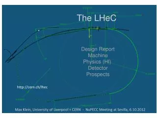
The LHeC Detector (introduction). http://cern.ch/lhec. P. Kostka, A. Polini. Outline: Experiment requirements and accelerator boundaries (Physics, Machine, Interaction Region and Detector) Present Detector Design Detector Session and Workshop Discussion Future and Outlook.

E N D
The LHeC Detector(introduction) http://cern.ch/lhec P. Kostka, A. Polini Outline: • Experiment requirements and accelerator boundaries (Physics, Machine, Interaction Region and Detector) • Present Detector Design • Detector Session and Workshop Discussion • Future and Outlook
Kinematics & Motivation (60 GeV x 7 TeV ep) s= 1.4 TeV New physics, distance scales few . 10-20 m Large x partons High precision partons in LHC plateau • High mass (Meq,Q2) frontier • EW & Higgs • Q2 lever-arm at moderate & high x PDFs • Low x frontier [ x below 10-6 at Q2 ~ 1 GeV2 ] novel QCD … Nuclear Structure & Low x Parton Dynamics High Density Matter
LHeC Kinematics • High x and high Q2: few TeV HFS scattered forward: Need forward calorimeter of few TeV energy range down to 10o and below █. Mandatory for charged currents where the outgoing electron is missing. Strong variations of cross section at high x demand hadronic energy calibration as good as 1% • Scattered electron: Need very bwd angle acceptance for accessing the low Q2 and high y region █.
Design Approach • Provide a baseline design which satisfies the Physics requirements along with the constraints from the machine and interaction region for running during the PHASE II of LHC • Having to run along with the LHC, the detector needs to be designed and constructed in about 10 years from now to be able to run concurrently with the other LHC experiments designed for pp and AA studies in the ep/eA mode, respectively. • While avoiding large R&D programs, the final LHeC detector can profit from the technologies used nowadays at the LHC and the related developments and upgrades • Modular and flexible accommodating upgrade programs; Detector assembly above ground; Detector maintenance (shutdown) • Affordable - comparatively reasonable cost. • More refined studies are required and will follow with the TDR and once a LHeC collaboration has been founded
Two Alternative Designs 10 GeV 10, 30, 50 GeV 10 GeV • Ring-Ring • e-p and e-A (A=Pb, Au, …) collisions • More “conventional” solution, like HERA, no difficulties of principle - at first sight - but constrained by existing LHC in tunnel • polarization 40% with realistic misalignment assumptions • Linac-Ring • e-p and e-A (A=Pb, Au, …) collisions, polarized e from source, somewhat less Luminosity/Power • New collider type of this scale
ep ep LR Option - Beam & Fan Envelopes RR Option - Beam & Fan Envelopes x [mm] x [mm] Triplet Position z= ~10m Triplet Position z= ~22m z [mm] z [mm] LR, RR option - Beam & SR SR Fangrowth with z Legend : Dipole SR Fan growth with z (high luminosity case)
Photon Number Density at the IP 3 beams, head‐on collisions SR y [mm] p-beam 2 p-beam 1 x [mm] e-beam LR Interaction Region • Special attention is required to the interaction region design, which comprises beam bending (in/out), direct and secondary synchrotron radiation, vacuum and beam pipe • Dipoles around the IP(2 x 9m, 0.3T) for making electrons collide head-on with p-beam 2& safely extract the disrupted electron beam. • Simulation of Synchrotron Radiation (SR) load in the IR and design of absorbers / masks shielding SR from backscattering into the detector & from propagating with e± beam. • Beam pipe design - space for SR fan- tracking/calorimetry close to the IP / beam line (goal: 1°- 179°)
Beam Pipe / Profile - SR Fan Ring-Ring - Inner dimensions (masks at 6, 5, 4m - primary SR shield)Circular(x)=2.2cm (LHC upgrade); Elliptical(-x)=-5.5, y=2.2cmbeam pipe dimensions reduced - using static / movable masks; y=2.2cm housing beam/SR envelopes + 1cm safety margin x= -5.5cm x=2.2cm Linac-Ring - Inner Dimensions Circular(x)=2.2cm; Elliptical(-x)=-10., y=2.2cm y=2.2cm x= -10cm x=2.2cm
Linac Ring: Favored Option Linac-Ring: • Reduced impact on the LHC schedule • New Accelerator Design (Energy Recovery Linac) • Dipole Field along the whole interaction region • LHC Interaction Point P2
Requirements from Physics • High resolution tracking system • excellent primary vertex resolution • resolution of secondary vertices down to small angles in forward direction for high x heavy flavor physics and searches • precise pt measurement matching to calorimeter signals (high granularity), calibrated and aligned to 1 mrad accuracy • The calorimeters • electron energy to about 10%/ E calibrated using the kinematic peak and double angle method, to permille level Tagging of 's and backward scattered electrons - precise measurement of luminosity and photo-production physics • hadronic part 30%/ E calibrated with pt_e /pt_h to 1% accuracy • Tagging of forward scattered proton, neutron and deuteron - diffractive and deuteron physics • Muon system, very forward detectors, luminosity measurements
BST - ΔZ=8. cm min-inner-R = 3.1 cm; max-inner-R= 10.9 cm outer R = 46.2 cm Planes 1 - 3: z1-3 = -130. / -170. / -200. cm FST - ΔZ=8. cm min-inner-R = 3.1 cm; max-inner-R= 10.9 cm outer R = 46.2 cm Planes 1 - 5: z5-1 = 370. / 330. / 265. / 190. / 130. cm Central Si Tracker Central Pixel Tracker CST - ΔR 3.5cm each 1. layer: inner R = 21.2cm 2 layer: = 25.6 cm 3. layer: = 31.2 cm 4. layer: = 36.7 cm 5. layer: = 42.7 cm 4 layerCPT min-inner-R= 3.1 cm max-inner-R = 10.9 cm ΔR =15 cm Central Forward/Backward Tracker 4 CFT/CBT min-inner-R = 3.1 cm, max-inner-R= 10.9 cm Electromagnetic Calorimeter Forward Si Tracker Backward Si Tracker Tracking - High Acceptance Dominant forward production of dense jets; backward measurements relaxed
LicToy 2.0 Simulation - Simplified Geometry Tracker Simulation • Silicon: compact design, low budget material, radiation hard http://wwwhephy.oeaw.ac.at/p3w/ilc/lictoy/UserGuide_20.pdf
Tracker Simulation (ii) • Same plots (left) and (small) deterioration in case of innermost barrel layer failure (right) 90⁰ 90⁰ 1⁰ 1⁰ 1⁰ 1⁰ 90⁰ 90⁰
GEANT4 - Fluences • Similar studies being done with FLUKA • Most critical the forward region • Rates far lower than LHC (LHC ~5 x 10¹⁴)
Tracker Detector Technology • Choose among available technologies n-in-p ( sLHC ) or n+-in-n (ATLAS/CMS/LHCb) • Radiation hardness in LHeC not as challenging as in LHC • Silicon Pixel, Strixel, Strips • Detailed simulation to best understand the needs and implications • Readout/Trigger, Services, # silicon layers • Analog/Digital Readout • Modular structure for best replacement / maintenance and detector adoption: RR high luminosity / high acceptance running • Pixel Detector*) ( barrel CPT 1-4 and inner forward/backward FST/BST)
Services and Infrastructure • Detector of very compact design; It might be necessary to open places/grooves/tunnels for services affecting the aperture of the detector; Optimum between costs and detector acceptance needs to be found. • Service and Infrastructure need very careful design being the main contributor to Material Budget Tracker Material Budget
Solenoid Options Large Coil • Large Solenoid containing the Calorimeter • 3.5 T Solenoid of similar to CMS/ILC • Precise Muon measurement • Large return flux either enclosed with Iron or Option of active B shielding with 2nd solenoid Small Coil • Smaller Solenoid placed between EMC and HAC • Cheaper option • Convenient displacement of Solenoid and Dipoles in same cold vacuum vessel (Linac-Ring only) • Smaller return flux (less iron required) • Muon p, pt measurement compromised HAC EMC EMC EMC COIL
Magnets Baseline Solution: • Solenoid (3.5 T) + dual dipole 0.3 T (Linac-Ring Option) • Magnets (may be) embedded into EMC LAr Cryogenic System • Need of study the Calorimeter Performance and impact of dead material between EMC and HAC sections; it might be possible placing the magnet system even in front of the EMC - at even lower radius at just outside of the tracking system
Baseline Detector e∓ p/A
Electromagnetic Calorimeter (i) • Baseline Electromagnetic Calorimeter • LAr for barrel EMC calorimetry - ATLAS (~25-30 X0) • Advantage: same cryostat used for solenoid and dipoles • GEANT4 simulation (*) • Simulation results compatible with ATLAS • barrel cryostat being carefully optimized pre-sampler optimal • 3 different granularity sections longitudinally ATLAS ATLAS (*) F. Kocak, I. Tapan Uludag Univ.
Electromagnetic Calorimeter (ii) • Simulation with simplified design w.r.t.Atlas • LAr Calorimeter : good energy resolution, stable performance • Simulation results compatible with ATLAS • Warm (Pb/Sci) option also investigated • 30X0 (X0(Pb)=0.56 cm; 20 layers) LHeC F. Kocak, I. Tapan Uludag Univ.
Hadronic Calorimeter (i) • Baseline Design • HAC iron absorber (magnet return flux) • scintillating plates (similar to ATLAS TILE CAL) • Interaction Length: ~7-9 λI • Setup: • GEANT4 simulation (*) • performance optimization: • containment, resolution, combined HAC & EMC response • solenoid/dipoles/cryostat in between (*) F. Kocak, I. Tapan Uludag Univ.
Hadronic Calorimeter (ii) • Preliminary studies on impact of the magnet system on calorimetric measurements (GEANT FLUKA) • Energy resolutions • Shower profiles F.Kocak, I.Tapan, A.Kilic, E.Pilicer Uludag Univ.; E.Arikan, H.Aksakal Nigde Univ.
Endcap Calorimeters Forward/Backward Calorimeters • Forward FEC + FHC: • tungsten high granularity • Si (rad-hard) • high energy jet resolution • FEC: ~30X0; FHC: ~8-10 λI • Backward BEC + BHC: • need precise electron tagging • Si-Pb, Si-Fe/Cu (~25X0, 6-8 λI ) • GEANT4 simulation * • containment, multi-track resolution (forward) • e± tagging/E measurement (backwards) * A. Kilic, I. Tapan - Uludag University
Forward/Backward Calorimeters • Highest energies in forward region • Radiation hard • High Granularity • Linearity
Muon System Baseline Baseline Solution: • Muon system providing tagging, no independent momentum measurement • Momentum measurement done in combination with inner tracking • Present technologies in use in LHC exp. sufficient (RPC, MDT, TGC) dipole dipole e∓ p/A
Muon System Extensions Extensions: • Independent momentum measurement • Large solenoid (incompatible with LR dipoles) • Dual Coil System (homogeneous return field) • Forward Toroid System p/A e∓
Status and Outlook • A LHeC baseline detector concept has been presented • The design depends heavily on the constraints from the machine and interaction region • For all cases a feasible and affordable concept which fulfills the physics requirements has been presented • As a baseline many improvements available. A more precise design will follow from more detailed simulations, engineering and the knowledge of the machine constraints This Workshop • Start a new phase in detector design • Collect people, experience, information • Identify and address critical items, discuss the timeline for realization • Build a collaboration and move next steps towards a Technical Design
Detector Session Agenda Thursday: Friday:
Our Thanks to all who contributed, not only within the Detector Group, but also to the Physics, Interaction Region and Accelerator GroupsMany thanks also to the refereesPhilip BlochRoland Horisberger