Download
1 / 39
390 likes | 490 Vues
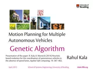
Motion Planning for Multiple Autonomous Vehicles . Lateral Potentials Elastic Strip. Rahul Kala.

E N D
Motion Planning for Multiple Autonomous Vehicles Lateral Potentials Elastic Strip Rahul Kala • Presentation of paper: R. Kala, K. Warwick (2013) Planning Autonomous Vehicles in the Absence of Speed Lanes using an Elastic Strip, IEEE Transactions on Intelligent Transportation Systems, 14(4): 1743-1752.
Why Lateral Potentials? • Computational Time • Work with partially known environments Issues • Completeness • Optimality
Key Contributions • Modelling of lateral potentials suited for road scenarios to eliminate the known problems associated with the potential approaches. • Modelling of potentials based on the principles of time to collision and cooperation apart from the distance measures for lateral planning of the vehicles. • Use of obstacle and vehicle avoidance strategy parameters for higher order planning. • Heuristic decision making in deciding these strategy parameters for real time planning.
Artificial Potential Fields • Goal attracts the robot, obstacles repel, both inversely proportional to the distance • Robot moves due to forces due to both factors Attraction force from the goal Repulsive force from the obstacles Resultant force/ direction of motion Source: Tiwari R, Shukla A, Kala R. (2013) Intelligent Planning for Mobile Robotics: Algorithmic Approaches, IGI Global Publishers, doi: 10.4018/978-1-4666-2074-2. 4
Why not Artificial Potential Fields • Oscillations in narrow corridor scenarios (like roads) • A vehicle directly in front repels one at back; no overtake • Many zero potential areas • Cooperation weakly modelled
Lateral Planning Design methodology • Obstacles and road boundaries repel vehicle at the lateral side • The repulsion is used to decide the steering action • Sample out obstacles in a few directions • For each direction decide which side to steer and by how much
Lateral Potential Sources Side Diagonal Forward Back Side Diagonal
Lateral Potentials • All combined by a weighted addition (with sign), where weights are the parameters • Lateral potential gives the preferred orientation to the direction of the road • Required steering correction to get the correct orientation is applied (subjected to constraints)
Longitudinal Planning • Maximum speed as per the distances recorded is set • Distance recorded in longitudinal direction and in the heading direction of the vehicle • Maximum acceleration limited by aggression factor to eliminate steep acceleration/retardation
Elastic Strip • Imagine an elastic strip representing a trajectory between a source and destination • Each obstacle acts as a source of repulsion • The elastic strip has an internal force by which it attempts to straighten itself • As the obstacles move, the strip deforms • At any time the strip represents the trajectory Elastic Strip
Key Contributions • Design of a method to quickly compute the optimal strategy for obstacle and vehicle avoidance, and the associated trajectory. • Real-time optimization of the trajectory as the vehicle moves, making the resultant plan near-optimal. • Using heuristics to ensure the travel plan is near-complete. • Making the coordination strategy cooperative between vehicles.
Why Elastic Strip And not Lateral Potentials • Make the resultant approach complete • Make the resultant approach optimal • Fixing strategy parameters
Objectives Used to select between any competing plans at any instance of time • Go as far as possible longitudinally • Maximize lateral clearance (distance from side obstacles) • Minimize travel time • Maximize cooperation • Application of lateral potential strategy heuristic
Feasibility • All other vehicles assumed to be travelling at the same speed and orientation Any point which would be occupied by the vehicle being planned can be called feasible only if: • It allows enough time for to slow down to avoid collision from the vehicle in front • It allows enough time for the vehicle at back to slow down to avoid collision from the vehicle located at the point • No collisions with obstacles or the other vehicles A plan is feasible if all points in it are feasible
General Framework • Make plan as the vehicle moves • Start will a null plan • As the scenario changes: • speed is set to the maximum value as per the current position • infeasible part is deleted • plan is extended • plan is optimized
Modes of operation Trajectory (overcoming obstacle not possible due to blue vehicle) do Obstacle Obstacle only trajectory Need to stop here. On going further there is a risk of stopping too close to the obstacle, preventing further motion even by greatest steering. More close the trajectory to the trajectory without obstacle, more away is the final position of the vehicle from the obstacle, lesser the do.
Plan ends with static obstacle Mode Plan does not end with static obstacle Compute maximum speed Trim Plan Optimize Plan Extend Plan Map Current Plan Control Vision General Framework
Plan Extension • The strategy corresponding to the selected best plan is used for further plan extension calls • If the plan ends with an obstacle • additionally an obstacle only trajectory is computed • main trajectory is re-generated using the strategy that resulted in obstacle only trajectory • this results in similarity between an obstacle only trajectory and the main trajectory
Plan Extension All plans Optimal plan
Plan Optimization • A trajectory represents an elastic strip • A number of waypoints are uniformly taken at the strip • Each waypoint is acted upon by forces by which it moves • Weighted addition of forces is taken • Only lateral component of the force is considered
Path Optimization • Main trajectory or obstacle free trajectory Main Trajectory – if followed, gets the vehicle too close to the obstacle Obstacle Drift Obstacle only trajectory – if followed, vehicle would need to wait for the blue vehicle very early Concept: Drift main trajectory towards obstacle free trajectory as long as collision with blue vehicle can be avoided
Path Optimization Actual position Repulsion by blue vehicle Projected position at the time of arrival Repulsion by road boundary and green vehicle Elastic Strip Spring attractive force
Plan Optimization Initial Plan Optimized plan (with the sole aim of maximizing the average clearance) Optimized plan
Thank You • Acknowledgements: • Commonwealth Scholarship Commission in the United Kingdom • British Council