Download
1 / 10

E N D
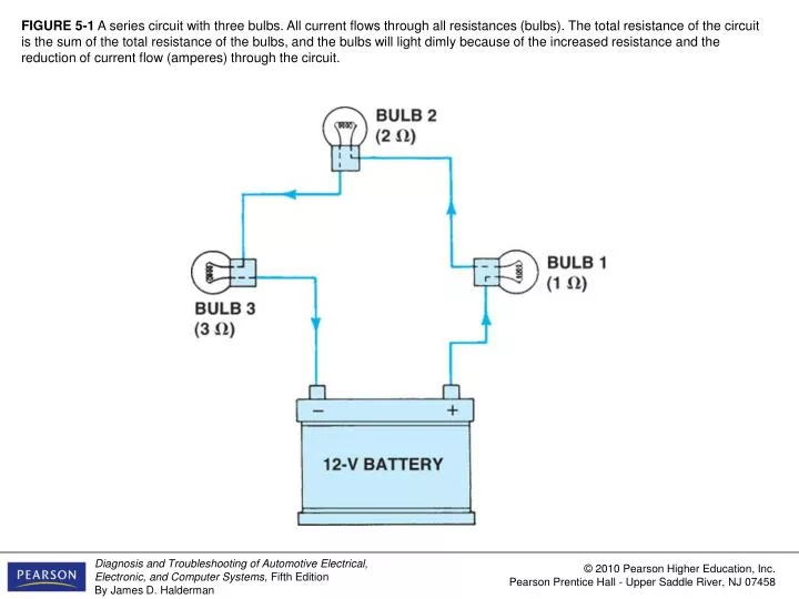
FIGURE 5-1 A series circuit with three bulbs. All current flows through all resistances (bulbs). The total resistance of the circuit is the sum of the total resistance of the bulbs, and the bulbs will light dimly because of the increased resistance and the reduction of current flow (amperes) through the circuit.
FIGURE 5-3 As current flows through a circuit, the voltage drops in proportion to the amount of resistance in the circuit. Most, if not all, of the resistance should occur across the load such as the bulb in this circuit. All of the other components and wiring should produce little, if any, voltage drop. If a wire or connection did cause a voltage drop, less voltage would be available to light the bulb and the bulb would be dimmer than normal.
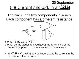
FIGURE 5-4 In a series circuit, the voltage is dropped or lowered by each resistance in the circuit. The higher the resistance, the greater the drop in voltage.
FIGURE 5-5 A voltmeter reads the differences of voltage between the test leads. The voltage read across a resistance is the voltage drop that occurs when current flows through a resistance. A voltage drop is also called an “IR” drop because it is calculated by multiplying the current (l) through the resistance (electrical load) by the value of the resistance (R).
FIGURE 5-6 In this series circuit with a 2 ohm resistor and a 4 ohm resistor, the current (2 amperes) is the same throughout, even though the voltage drops across each resistor.


![[Series Circuit]](https://cdn1.slideserve.com/2747272/series-circuit-dt.jpg)