Download
1 / 42
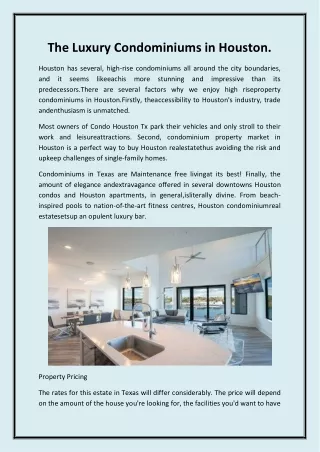
420 likes | 533 Vues
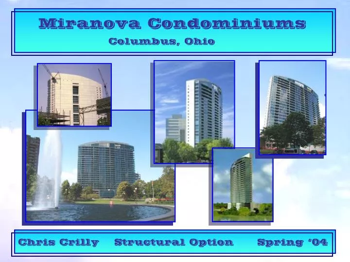
Chris Crilly. Structural Option. Spring ‘04. Miranova Condominiums. Columbus, Ohio. Presentation Outline. Project Background. Existing Conditions. Problem Statement. Goals. Proposed Solution. Floor System. Lateral System. Other Considerations. Acoustics. Construction Management.

E N D
Chris Crilly Structural Option Spring ‘04 Miranova Condominiums Columbus, Ohio
Presentation Outline • Project Background • Existing Conditions • Problem Statement • Goals • Proposed Solution • Floor System • Lateral System • Other Considerations • Acoustics • Construction Management • Summary/Conclusions • Acknowledgments • Questions
N I-70 Project Background Location • Columbus, Ohio • Adjacent to I-70 • Along Scioto River • Faces North into the city
Construction Dates • Groundbreaking was in July of 1998 • Substantial Completion was in October of 2000 • Tenant fit out continued into 2002 Size • Gross Building Area • Garage - 123,254 SF 5 Stories • Tower - 332,862 SF22 Stories • Total - 456,116 SF 27 Stories Cost • $52 Million Total Cost Project Background
Project Background Building Occupancy • Basement • Visitor Parking • Ground Floor • Reception/Lobby • Storage • Social Spaces • Offices • Fitness Areas • Levels 2-4 • Resident Parking • Small Storage Spaces • Levels 5-28 • Condominiums • Approximately 146 High-end • Luxury Condominiums • Approximately 226 Total parking • Spaces
Project Background Project Team • Design Architect – Arquitectonica • Architect of Record – HKS Inc. • Structural Engineer – The Thornton–Tomasetti Group • MEP Engineer – Flack & Kurtz Consulting Engineers • Lighting Designer – Lighting Design Alliance • Civil Engineer – E M H & T, Inc. • Construction Manager – Turner Construction Company • Wind Tunnel Consultant – Cermak Peterka Peterson, Inc.
Existing Conditions Architecture • North Façade – Blue Tinted Glass Curtain Wall • Other Façades – 6” Precast Conc. Panels • Level 1 – 5 • 120’ x 250’ • Tower • 60’ x 280’ • 655’ Radius
Existing Conditions Structure – Foundation • Concrete Mat Foundation • f’c = 4000 psi – Normal Weight Concrete • Placed on a 2” Mud Slab • 5’-3” to 5’-9” thick under the tower • 2’-9” to 3’-3” thick under 5 story portion
Existing Conditions Structure – Floor System • 8” Post-Tensioned Flat Plate • f’c = 5000 psi – Normal Weight Conc. • Post Tensioning • ½” , 270 ksi Low-Relaxation Strands • Banded in 6’ Width over Col. Lines in E/W Direction • Uniformly Spaced in N/S Direction
Existing Conditions Structure – Lateral System • Concrete Shear Walls • f’c = 5000 psi – Normal Weight Conc. • Thickness Decreases up the Building • 22” to 12” Thick
Goals/Criteria Problem Statement • Possibility exists for owner to purchase to adjacent units • and connect the two to make a larger living space • Very difficult and expensive to execute future expansions: • Vertically – due to post-tensioned slabs • Horizontally – due to R/C shear walls
Goals Goals/Criteria • Allow greater and cheaper flexibility for possible future • renovations • Vertically • Horizontally • Minimize impact on overall cost • Minimize impact on architecture
Proposed Solution Floor System • Steel Systems • More flexible to future changes than concrete • Easier to add openings for stairways and ducts • Lighter • Steel floor systems are typically deeper • I will concentrate on Low Floor-to-Floor systems • to minimize impact on architecture and cost
Proposed Solution Lateral System • Steel Braced Frames • More flexible to future changes than concrete • shear walls • Easier to add openings for doorways • Lighter • Braced frames allow for only discrete door locations • I will concentrate on maximizing the area for door • openings for greater future flexibility
Connection • L4x4x12x3” Erection • Angle • 3 – 1/2” Erection • Bolts Floor System • Composite Slab and Beam System • Slight modification to Beam-Girder connections • over typical connections • Reduces floor depth • Reduces fabrication time and costs
Floor System • Infill Beams (N-S Span Direction) • W10 x 22 – Center Bay • W10 x 17 or W10 x 19 – Outer Bays • Girders (E-W Span Direction) • W12 x 26 to W12 x 40 • ΔEL b/w TopBeam and TopGirder • 1.625” – 1.875” • Allows for 1/8” Mill Tolerance • 2” Max Required - 2” – 18 gage VLI Deck
Connection Check Floor System • Yield Line Analysis • Initially Studied by W. S. Easterling of Va. Tech. • Followed up with Master’s Thesis by Wey-Jen Lee • at Va. Tech R = Nominal Strength of Girder Flange Fy = Yield Strength of Girder tf = Thickness of Girder Flange bb = Width of Beam Flange bg = Length of Girder Flange (bf/2 – k1) D = Length of Beam Bearing φ = 0.9 - Assumed
Connection Check Floor System • These Capacities are CONSERVATIVE. Why? • Proven by experimental tests • Bearing point is assumed to be at Center of Bearing Area • Connection similar to un-stiffened seated connection • Bearing point determined by beam web limits states • simultaneously with bending limit state • Beam Web Limit states were also checked and found to be OK
Floor System Other Design Considerations • Sound & Impact Transmission through floor system • Investigated under Acoustic Breadth • Floor Vibrations • Typical beams checked • Interior Bays • Fell in upper half of barely perceptible range of the modified R-M scale • Max. acceleration – 0.339% < 0.5% OK • Exterior Bays • Fell in lower half of slightly perceptible range of the modified R-M scale • Max acceleration – 0.495% < 0.5% OK
Floor System Typical Composite System • A typical composite floor system was also designed • Typical connections • No depth restrictions • Partially composite beams • Same beam and girder layout was used • Infill Beams – W12x19 • Girders – W16x26 to W16x30 • Beam to Girder Connections – Shear Tab • (3) – ¾” A325 Bolts • PL – 3/8” x 4 ½” x 9” A36 • 5/16” fillet weld • φRn = 27.8 k
Cost & Time Advantages Floor System • This was done to compare: • Material costs • Fabrication costs • & • Fabrication time • Shallow System • Heavier Members • Slightly more shear studs • Less Connection Material • Less Beam Fabrication (Copes)
Lateral System • Combination of R/C shear walls and steel braced • frames • Shear Walls • Keep existing walls around 2 building cores • Walls added around building core • Better protection in emergencies • Stiffens building • Steel Braced Frames • Replace large shear walls in N-S Direction • 3 options studied to: • Determine most efficient system • Determine most economical system • Maximize available space for future doors
Lateral System • Option #2: Outer Braces • Center Brace – Same as • option #1 • Option #1: All Braces
Lateral System • Option #3: Eccentrically Braced Frames • Design Summary • 4 ft link in larger bay • Ext. Columns – W14x426 to W14x48 • Int. Columns – 2 to 3 sizes smaller • Beams – W16x45 to W18x60 • Braces – W12x40 to W12x45 • Pros • 4X area for doors in center frame • 2X area for doors in outer frames • Smaller Columns • Acceptable building and story drifts • Cons • Slightly larger beams • Approx. 2X # bracing connections • Approx. 2X # braces
Final Design Outer Braces Center Brace Lateral System
Lateral System • Comparison b/w Existing and Proposed System
Level 5 Diaphragm • Existing Building used Wind Loads from wind • tunnel test • I used Code stipulated loads • which were larger • Change in lateral system at level 5 caused large shears in diaphragm • Check proved existing diaphragm to be adequate
Impacts on Arch. • 15 ft Building height increase over 20 stories • Locations of existing doors in shear walls had to be slightly • moved to accommodate the braces, did not greatly impact • space layouts • 3 additional columns – easily hidden • 8” increase in party wall thickness – 4” loss of living space on • each side
Acoustics Floor System • Building Code Design Criteria: • STC 50 • IIC 50 • Fire Rating – 2 HR • Recommended Design Criteria for Luxury Residences: • STC 60 • IIC 60
Acoustics • Properties • STC 62 • IIC 74 – with carpet • IIC 60 – with hard flooring on foam rubber underlay • Fire Rating – UL No. D916 – 2 HR rating with 3 ½” slab • Actual slab is 4 ¼”
Brace Infill Wall Acoustics • Building Code Design Criteria: • STC 50 • Fire Rating – 1 HR • Recommended Design Criteria for • Luxury Residences: • STC 60 • Properties: • STC 60 • Fire Rating – UL No. U411 • 2 HR
Constr. Management Cost Estimate
Constr. Management Cost Estimate
Constr. Management Cost Estimate
Constr. Management Site Logistics
Summary/Conclusion System Comparison
Bottom Flange Bearing Beam-to-Girder System With Eccentric Chevron Bracing in larger Bays Summary/Conclusion Conclusion
Acknowledgments • AE Faculty • Dr. Geschwindner – for all of the help and guidance throughout the year • Dr. Hanagan – for guidance in understanding new connections • Courtney Burroughs – for guidance on acoustical design • All other AE faculty – for getting me to the point where I could complete this • Project Team – for allowing me to use the building and providing required materials • - Pizutti Companies - Robert Sedlak, Flack & Kurtz • - Kirby Chadwell, HKS Inc. - Leighton Cochran, CPP • - Aine Brazil, The Thornton-Tomasetti Group • Jeremy Smith, Altoona Pipe & Steel Co. – for all the help in estimating steel costs • Melissa Toth, P.E. – for all the help, guidance and insight into the AE Thesis Experience • My Parents – for guidance, support, and giving my the opportunity to attend PSU and make • my dreams come true. • Friends & Family – for all the support over the past five years • Sarah Steeves – for putting up with me over the past few months while I was constantly busy • with thesis
Questions Miranova Condominiums Columbus, Ohio Chris Crilly Structural Option Spring ‘04
Foundation • 3 additional columns added • Reduction of 250k to 750k in tower column • loads • Average of 250k net uplift in braced frame cols. • Smaller loads would allow for significantly reduced • thickness in mat at most locations • Existing mat would require extra tension reinforcement to • distribute uplift forces over area in which mat can resist them • Wide flange or channel shapes
Other Issues Constr. Management • Steel Lead Time • Excavation and construction of foundation & first five stories will provide sufficient time for steel to be on sight • Required lead time will not delay schedule • Schedule Impact • Only rough calculations performed • Steel structure can be erected faster than existing concrete structure • Additional gypsum board, glass fiber insulation, and curtain wall will add time to schedule • Overall schedule construction duration not effected