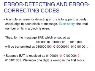
Download
1 / 24
250 likes | 470 Vues
Error-Correcting Codes for TLC Flash. Eitan Yaakobi, Laura Grupp Steven Swanson, Paul H. Siegel, and Jack K. Wolf. University of California San Diego. Flash Memory Summit, August 2011. Outline. Flash Memory Structure Partial Cell Usage in TLC Flash ECC Comparison for TLC Flash

E N D
Error-Correcting Codes for TLC Flash Eitan Yaakobi, Laura Grupp Steven Swanson, Paul H. Siegel, and Jack K. Wolf University of California San Diego Flash Memory Summit, August 2011
Outline • Flash Memory Structure • Partial Cell Usage in TLC Flash • ECC Comparison for TLC Flash • New ECC Scheme for TLC Flash
SLC, MLC and TLC Flash High Voltage High Voltage High Voltage SLC Flash TLC Flash MLC Flash 1 Bit Per Cell 2 States 2 Bits Per Cell 4 States 3 Bits Per Cell 8 States Low Voltage Low Voltage Low Voltage
Flash Memory Structure • A group of cells constitute a page • A group of pages constitute a block • In SLC flash, a typical block layout is as follows
Flash Memory Structure MSB/LSB • In MLC flash the two bits within a cell DO NOT belong to the same page – MSB page and LSB page • Given a group of cells, all the MSB’s constitute one page and all the LSB’s constitute another page 01 00 10 11
Flash Memory Structure - TLC MSB Page CSB Page LSB Page MSB Page CSB Page LSB Page
Experiment Description • We checked several flash memory TLC blocks • For each block the following steps are repeated • The block is erased • A pseudo-random data is written to the block • The data is read and compared to find errors • Remarks: • We measured many more iterations than the manufacturer’s guaranteed number of erasures • The experiment was done in laboratory conditions and related factors such as temperature change, intervals between erasures, or multiple readings before erasures were not considered
Raw BER Results High Voltage Low Voltage
Partial Cell State Usage • Store either one or two bits in every cell • For one bit, only the MSB pages • For two bits, only the MSB and CSB pages • Two cases: • The partial storage is introduced at the beginning • The partial storage is introduced after 2000 normal program/erase cycles High Voltage Low Voltage
ECC Comparison • We evaluated different ECC schemes • BCH Codes • LDPC Codes • Gallager Codes • Protograph-based low-density convolutional codes • AR4JA protograph-based LDPC codes • LDPC codes taken from MacKay’s database of sparse graph codes
New ECC Scheme for TLC Flash • Errors are corrected in each page independently • In particular, in a group of MSB, CSB, and LSB pages sharing the same group of cells, errors are still corrected independently • Goal: to correct errors in a group of pages together • If a cell is in error, then with high probability one of the bits in the cell is in error
New ECC – Encoder • From every group of three pages we generate one page overGF(4) • Use two codes • A code over GF(4) – encodes the new page over GF(4) • A binary code – encodes the MSB pages s2 ∊GF(2)r2 C2Encoder s1 ∊GF(4)r1 pMSB = (p1,…,pn) ϕ C1 Encoder pCSB = (c1,…,cn) u = (u1,…,un) ∊GF(4)n pLSB = (l1,…,ln)
New ECC – Encoder • From every group of three pages we generate one page overGF(4) • Use two codes • A code over GF(4) – encodes the new page over GF(4) • A binary code – encodes the MSB pages s2 ∊GF(2)r2 C2Encoder s1 ∊GF(4)r1 pMSB = (p1,…,pn) ϕ C1 Encoder pCSB = (c1,…,cn) u = (u1,…,un) ∊GF(4)n pLSB = (l1,…,ln)
New ECC - Insights • If there is a cell error, then with high probability at most one of the bits in the cell is in error • The code over GF(4) find these one-bit cell-errors • However, it is still possible to see 2-bit and 3-bit cell errors • After the first stage, if a cell has 2- or 3-bit cel-errors, then all the bits are in error • The second code, working on the MSB bits, finds these errors
New ECC – Decoder s1 ∊GF(4)r1 p’MSB = (p’1,…,p’n) ϕ C1 Decoder p’CSB = (c’1,…,c’n) u’= (u’1,…,u’n) ∊GF(4)n p’LSB = (l’1,…,l’n) ψ s2 ∊GF(2)r2 e’ = (e’1,…,e’n) ∊GF(4)n C2 Decoder p’’MSB = (p’’1,…,p’’n) p’’CSB = (c’’1,…,c’’n) e’’ = (e’’1,…,e’’n) ∊GF(2)n p’’LSB = (l’’1,…,l’’n) + + + MSB Page CSB Page LSB Page
Summary • Partial Cell Usage in TLC Flash • ECC Comparison for TLC Flash • New ECC Scheme for TLC Flash • More analysis of codes and error behavior - COME TO BOOTH #115!
Acknowledgements • Aman Bhatia, Brian K. Butler, Aravind Iyengar, and Minghai Qin for their help in processing the error measurement results and, in particular, for the LDPC code performance simulations • Jeff Ohshima and Hironori Uchikawa for their collaboration and support from Toshiba