Download
1 / 49
570 likes | 756 Vues
Performance-based Leakage Reduction and Management Services SAWACO Zone 1 Training and Transfer of Technology. Outline. Classroom Training Modules Field Training Modules . Outline. Classroom Training Modules Module 1 DMA Design Module 2 DMA Construction and Commissioning

E N D
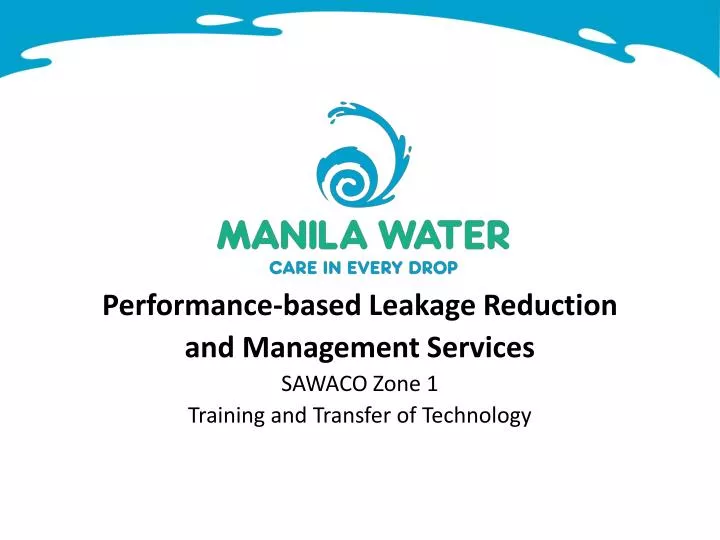
Performance-based Leakage Reduction and Management Services SAWACO Zone 1 Training and Transfer of Technology
Outline Classroom Training Modules Field Training Modules
Outline Classroom Training Modules Module 1 DMA Design Module 2 DMA Construction and Commissioning Module 3 Active Leakage Control Module 4 Pressure Management
Classroom Training Module 1DMA Design Definition of District Metering Area (DMA) is a world-wide accepted tool to operate and manage a network area wherein hydraulic boundary is defined by a system of Isolation Valves (IV) an flow Meters a discrete area of a water distribution network. It is usually created by closing boundary valves so that it remains flexible to changing demands. However, a DMA can also be created by permanently disconnecting pipes to neighboring areas. Water flowing into and out of the DMA is metered and flows are periodically analyzed in order to monitor the level of leakage
Classroom Training Module 1DMA Design Definition of District Metering Area (DMA) has water service connections ranging from 500-3,000 can be categorized into the following types: Single inlet DMAs Multiple inlet DMAs Cascading DMAs
Classroom Training Module 1DMA Design General Guidelines in DMA Design DMAs should not include trunk mains or storage tanks Each DMA should preferably be supplied through a single, metered supply point DMA boundaries should be created by closing boundary valves Variations in ground elevation should be minimal across the DMA The types of consumers and their respective water supply requirements should be assessed
Classroom Training Module 1DMA Design General Guidelines in DMA Design Legal regulations governing minimum pressures, local constraints due to topography and height of buildings as well as fire fighting requirements have to be respected Closing boundary valves to create DMAs will increase the number of dead-end pipes Pressure management plays a key role in leakage management
Classroom Training Module 1DMA Design Planning, Design and Engineering
Classroom Training Module 1DMA Design Planning, Design and Engineering
Classroom Training Module 1DMA Design Planning, Design and Engineering
Classroom Training Module 1DMA Design Planning, Design and Engineering
Classroom Training Module 1DMA Design Planning, Design and Engineering
Classroom Training Module 1DMA Design Planning, Design and Engineering
Classroom Training Module 1DMA Design Planning, Design and Engineering
Classroom Training Module 2DMA Construction and Commissioning
Classroom Training Module 2DMA Construction and Commissioning
Classroom Training Module 2DMA Construction and Commissioning Permit Acquisition
Classroom Training Module 2DMA Construction and Commissioning
Classroom Training Module 2DMA Construction and Commissioning Civil Works Line Meter Assembly Electromagnetic Flow Meter Pressure Reducing Valve Strainer By Pass Connection Panel Box
Classroom Training Module 2DMA Construction and Commissioning
Classroom Training Module 2DMA Construction and Commissioning Water Adequacy Test Water Adequacy Test will be conducted to ensure sufficiency of water supply within the isolated DMA despite of having only a single supply point WAT starts with the measurement of pressure at benchmark points within and outside of the DMA prior to and after closure of all isolation valves It is important that during the conduct of Water Adequacy Tests (WAT), all service connections covered by a particular DMA is identified, verified and tagged
Classroom Training Module 2DMA Construction and Commissioning Water Adequacy Test Steps Identify all boundary valves. Determine if the valves are operable, if not, replace the boundary valve. Monitor the pressure before and after isolation inside and outside the DMA Before closing any valve, install pressure gage in the hydrant inside the DMA Close the boundary valve one by one Continue closing all boundary valves Compare the pressure before and after the isolation If there is a big pressure drop, the DMA needs to be redesigned or introduce and additional supply usually by opening the critical boundary valve
M • Close all Isolation Valves • Let water pass thru District Meter (inflow &outflow). • If water is adequate within & outside the DMA, let all Isolation Valves be remained closed as supply will now pass through the District Meter. Check Pressure w/in & outside DMA Classroom Training Module 2DMA Construction and Commissioning 100mm 15 Water Adequacy Test 100mm 16 17 14 75mm 600mm CIP 13 1 2 150mm 150mm 4 11 5 3 100mm 75mm 12 10 200mm 18 150mm 26 27 25 9 8 100mm 19 7 20 21 100mm 6 75mm 600mm CIP 22 23 100mm 24
Classroom Training Module 2DMA Construction and Commissioning Zero Pressure Test ZPT is conducted following the Water Adequacy Test to ensure the tightness of isolations In principle, once all the isolation valves are closed including the inflow/s, pressure inside the DMA should drop to zero until no water comes out of the monitoring point/s The test is normally done during off-peak hours (1AM to 4AM), when demand is at its lowest and pressure is theoretically at its peak
Classroom Training Module 2DMA Construction and Commissioning Zero Pressure Test Steps Inform the customers about the schedule of the water interruption. Identify critical point, usually the hydrant in the lowest elevation of the DMA. Closed all the supply points Open the hydrant to check if there will be no water (preferably the hydrant in the lowest elevation inside the DMA). If there is still water after several minutes, check all the boundary valves if they are tightly closed. If all the boundary valves are fully closed and still there is water in the monitoring point, then there is unknown inflow inside the DMA. Check where the pressure is the highest as the unknown inflow may be in that area. Check old maps for old lines. Use GPR, pipe locator and other equipment to find old lines. Conduct step testing to localize the location of unknown lines.
Supply M • Unidentified night users • (0.06lpm/wm) Classroom Training Module 2DMA Construction and Commissioning Water Adequacy Test -Leaks (Physical Loss) 13 13 13 1 1 1 2 2 2 4 4 4 11 11 11 5 5 5 3 3 3 12 12 12 10 10 10 9 9 9 -Identified Night Users 8 8 8 7 7 7 Supply= Allowable Night Flow + Physical + Identified Night Users 6 6 6 Physical Losses= Supply- Allowable Night Flow -Identified Night Users
Classroom Training Module 2DMA Construction and Commissioning Baseline Measurement If Water Adequacy and Zero Pressure Test are successful, the next step is to conduct the baseline measurement Baseline Measurement is done to determine the baseline NRW of a particular DMA Baseline measurement is usually done on the period of 7 days to capture one complete cycle of water consumption pattern in the DMA
Classroom Training Module 2DMA Construction and Commissioning Baseline Measurement Steps Identify all the water service connection inside the DMA based on the design boundary. Identify and replace all defective water meters before baseline measurement to increase the accuracy of data. Carry out the baseline measurement. Read all DMA meters (inflow and outflow) on the 1st and 7th day, ideally at the same time. Compute Qi in m3/day. Read all customer meters on day 1 and 7 of the measurement. First and second reading of a specific meter should be at approximately the same hour of the day. Calculate the total metered consumption of all customers in the DMA by utilizing the 90 day billing average from SAWACO or JSC and calculate the daily average QM (m3/d). Calculate baseline leakage
Classroom Training Module 2DMA Construction and Commissioning Baseline Measurement Formula Lb = Qi – Qm Where Lb= Leakage during baseline in m3/day Qi = DMA inflow in m3/day Qm= metered consumption (billed volume) in m3/day
Classroom Training Module 2DMA Construction and Commissioning Data Logging and Data Transfer
Classroom Training Module 3Active Leakage Control Four Pillars of Physical Loss Management Water Losses due to Leakage
Classroom Training Module 3Active Leakage Control Step Testing Step testing is the technique whereby a leak or leaks are detected by making temporary successive valve closures to reduce the size of a DMA The valves are closed for a short duration whilst simultaneously measurements of the rate of flow are being made
Classroom Training Module 3Active Leakage Control Step Testing Procedure Survey and check the operability of all the existing valves inside the DMA. Plan the sequence of step test segment carefully utilizing the information gather from the valve survey. Schedule the activity during minimum demand usually 12:00 – 4:00 am. Inform the customers in advance regarding the Step test activity. Start closing the valves from the segment farthest from the line meter. Record valve details (location and no. of turns) and time of closure; Read the transmitter (totalizer and instantaneous flow) after every valve closure or set data logging every minute for more comprehensive data.
Classroom Training Module 3Active Leakage Control Step Testing Procedure Continue the step test until all segment are completed, the last segment being the area supplied by the line meter. If possible, check if there is no water in each segment. Open the valves slowly in reverse order. Do flushing activity to avoid dirty water complaint. Analyze the step test data to determine the segment with the highest possible leakage.
If DM has no Data Logger, read mtr. @ 5 min. interval This is done 15min before the 1st STV is closed up to the last STV is re-opened. Upload Mtr (if Logger Ready) Classroom Training Module 3Active Leakage Control Step Testing 13 13 13 1 1 1 2 2 2 4 4 4 M 11 11 11 M M 5 5 5 3 3 3 12 12 12 10 10 10 9 9 9 8 8 8 7 7 7 • Close Step-Test Valves @ 15min interval 6 6 6 • Open Step-Test Valves @ 15min interval (REVERSE OPERATION)
Classroom Training Module 3Active Leakage Control 100WSC Step Testing 350 lpm Highest physical loss 13 13 13 1 1 1 2 2 2 150WSC 4 4 4 M 11 11 11 M M 5 5 5 3 3 3 195 lpm 12 12 12 10 10 10 1145 lpm 600 lpm 795 lpm 195 lpm 9 9 9 8 8 8 7 7 7 500WSC 6 6 6
Classroom Training Module 3Active Leakage Control Equipment Ground Microphone Leak Noise Loggers GPR Leak Noise Correlators
Classroom Training Module 3Active Leakage Control Leaks commonly occur on: Service Connection Service pipe Tapping House meter assembly Mainline Main pipe Joints Valve
Classroom Training Module 4Pressure Management Definition of Pressure Management the practice of managing system pressures to the optimum levels of service ensuring sufficient and efficient supply to legitimate uses and consumers, while reducing unnecessary excess pressures, eliminating transients and faulty level controls all of which cause the distribution system to leak unnecessarily
Classroom Training Module 4Pressure Management Zone 1 Experience the overall aim is to ensure that the pressure during the day is not significantly lower that the pressure at night. To keep the pressure within optimal levels inside the DMA, PRVs previously installed with the rest of the flow meter set assembly will be operated
Classroom Training Module 4Pressure Management Pressure Reducing Valve (PRV) maintains the optimum pressure in the network at all times, but automatically compensates for the reduced flow following the repair of the leaks whilst maintaining the original operating pressures in the DMA
Classroom Training Module 4Pressure Management Pressure Management and Modulation
Classroom Training Module 4Pressure Management Pressure Management and Modulation Modulation Location Local point pressure modulation Critical point pressure modulation Modulation Type Fixed outlet pressure modulation Time-based pressure modulation Flow-based pressure modulation
Outline Field Training Modules Water Adequacy Test Zero Pressure Test Step-Testing Use of leak noise correlator Use of leak pen in leak detection Use of ground microphone for leak detection Line meter and PRV operation PMAC Familiarization/ Data Center