Download
1 / 11
130 likes | 295 Vues
Basic Electrical Circuits & Machines (EE-107). Course Teacher Shaheena Noor Assistant Professor Computer Engineering Department Sir Syed University of Engineering & Technology. Basic Nodal and Mesh analysis. In this chapter, we introduce two different ways to view electric circuits.

E N D
Basic Electrical Circuits & Machines (EE-107) Course Teacher ShaheenaNoor Assistant Professor Computer Engineering Department Sir Syed University of Engineering & Technology.
Basic Nodal and Mesh analysis In this chapter, we introduce two different ways to view electric circuits.
Basic Nodal and Mesh Analysis • Nodal Analysis: • It is based on KCL. • Mesh Analysis: • It is based on KVL. • Both methods allow to construct equations for a wide variety of circuits.
Nodal Analysis Method: • Use when (normally) multiple sources are present. • Convert voltage sources into current sources. • Identify all the nodes and choose a reference node. • All the nodes (except reference node) are then numbered and their corresponding voltages are designated. V1, V2, . . .
Nodal Analysis Steps: • We will assume V1 > V2 > V3... > 0. • Draw an arrow beside each passive component (resistor) showing the direction that current flows through it (made on the assumption made in step 1. For example) • The arrow is drawn from V1 towards V2, because current always flow from the higher voltage node to the lower voltage node. • Label each arrow with the current it represents, expressed in term of node voltages. 5. Write KCL at each node and solve the equations
Nodal AnalysisDrill Problem 4.1 (Page 71) • For the circuit given below, compute the voltage across each current source.
Nodal Analysis(Drill Problem 4.2) Page 74 • For the circuit given below, compute the voltage across each current source.
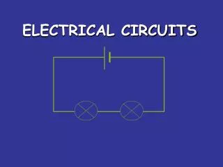
Mesh Analysis • Mesh analysis requires that all the sources in a circuit be voltage source. • The next step is to draw closed loops in the circuit, each loop representing a path around which KVL will be written. • The direction of each loop is arbitrary. • It may be either clockwise or counter clockwise.
Mesh Analysis It is convenient to think of each loop as representing a current that flows around the loop and we designate each by an appropriate symbol I1, I2 and so on. These loop currents are the unknowns in the set of simultaneous equations that results when KVL is written around each loop. Thus the number of unknown (loop currents) is the same as the number of equations.
Mesh AnalysisDrill Problem 4.5 (page 80) • Determine i1 and i2 in the circuit shown below.
Mesh AnalysisDrill Problem 4.6 (page 80) • Determine i1 and i2 in the circuit given below: